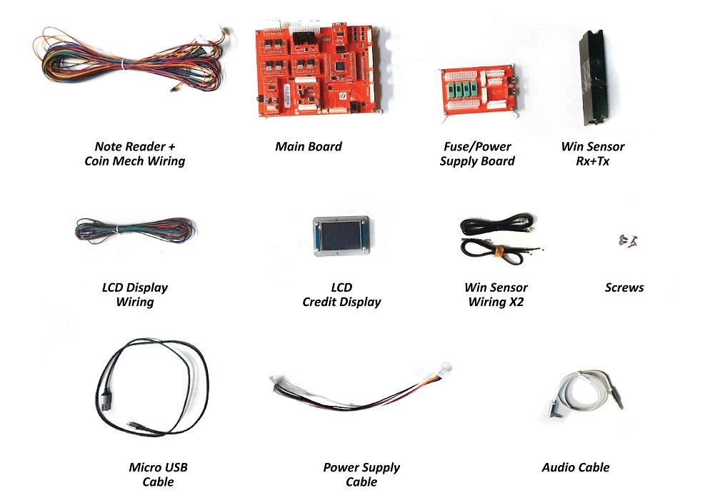
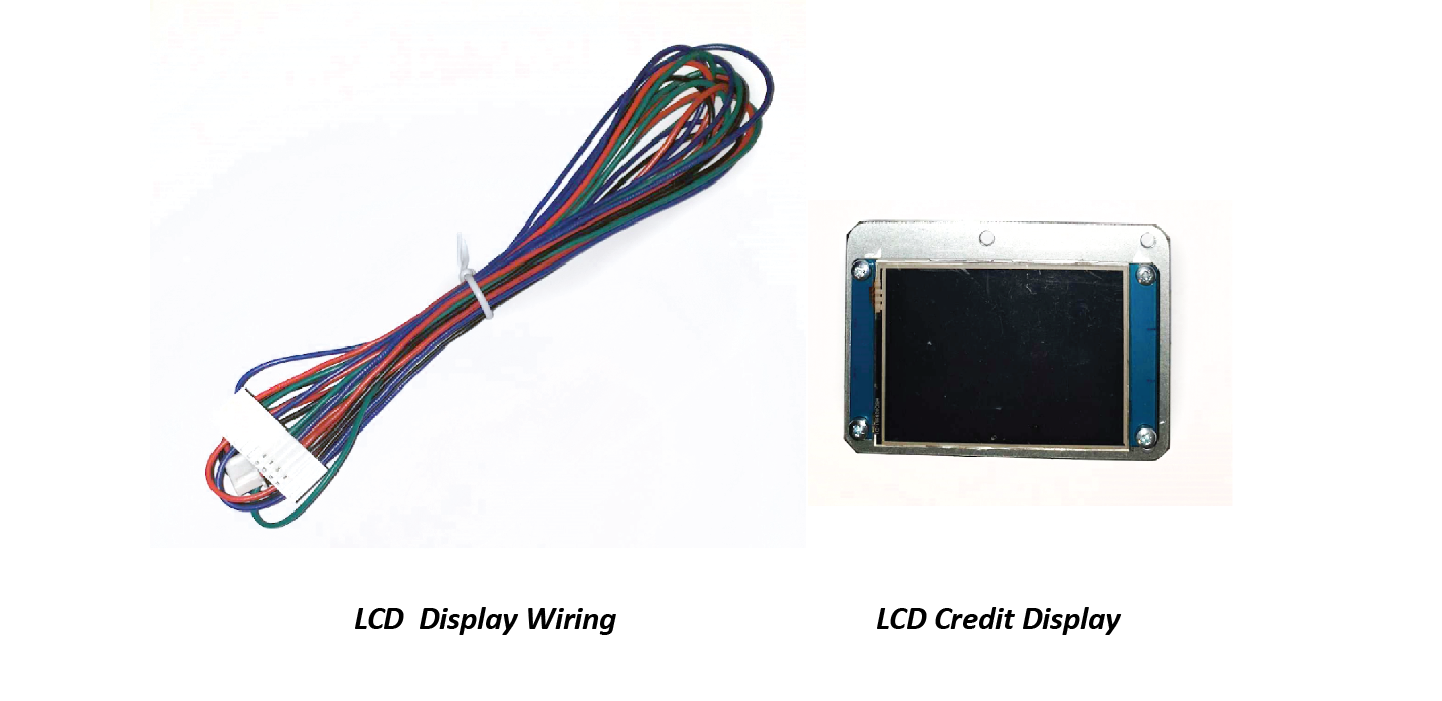
Parts Needed:
Step 1: Unplug wiring for the Coin Mech & Note Reader
Unplug the wiring from the Coin mech and note reader.
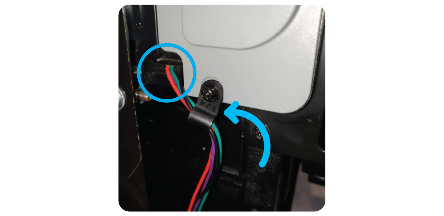
Remove the wire attached to the s crew on the note reader and take this with you.
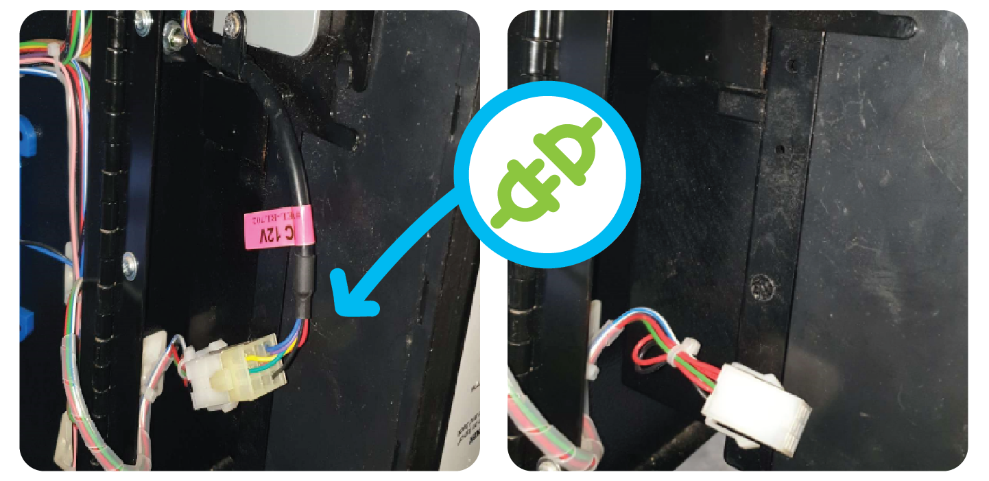
Remove the wire leading to the coin mech and Cable tie it so it doesn’t become an obstruction.
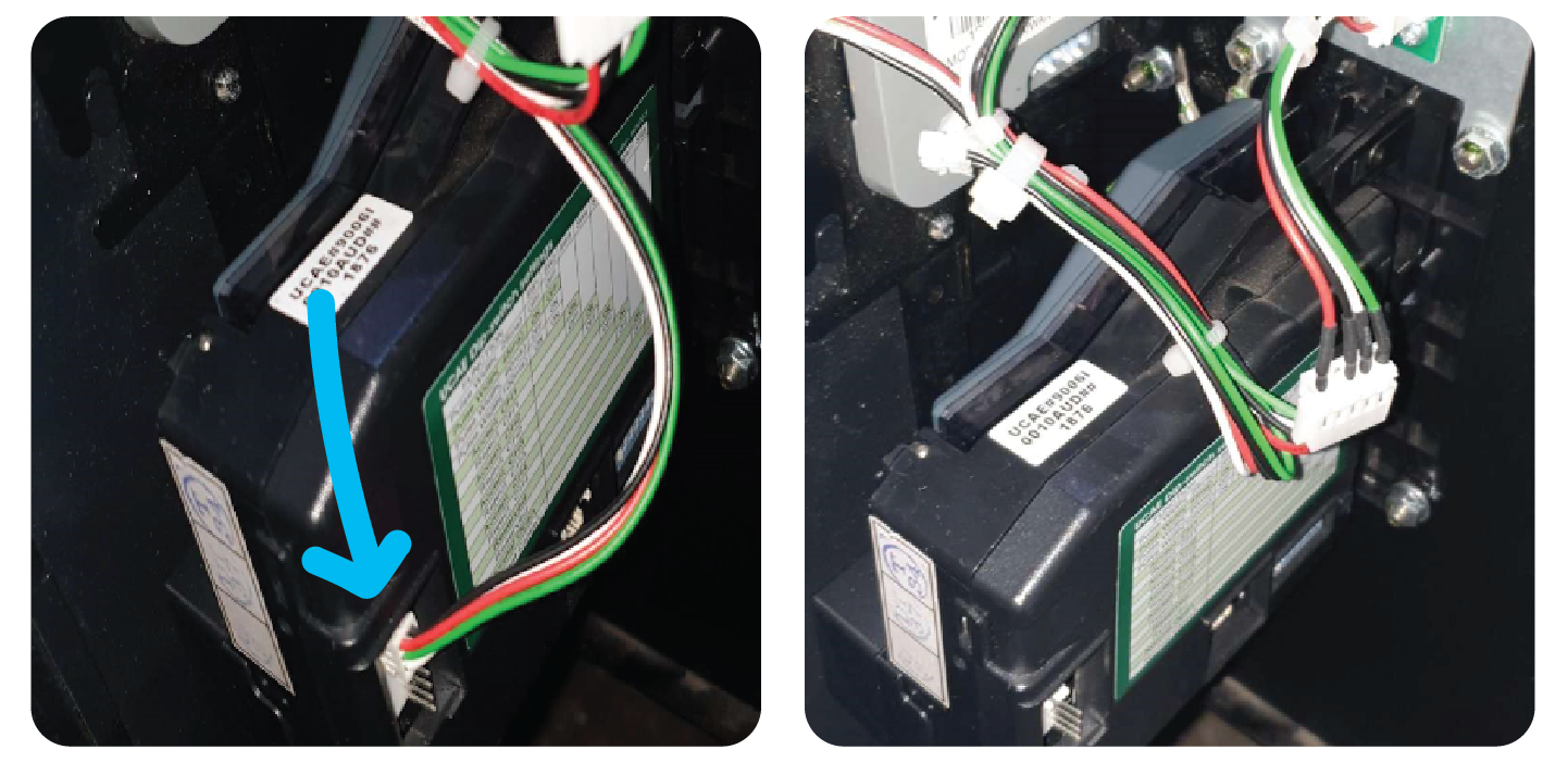
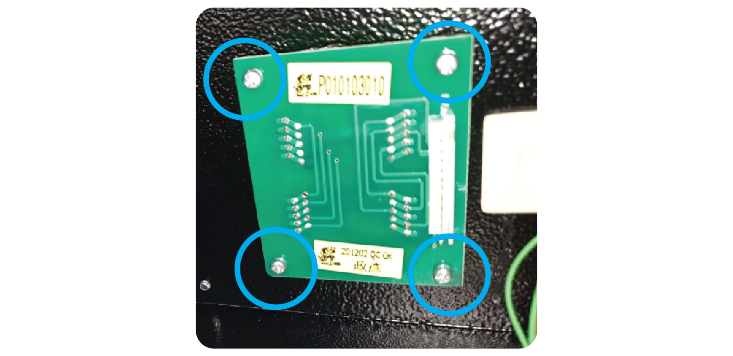
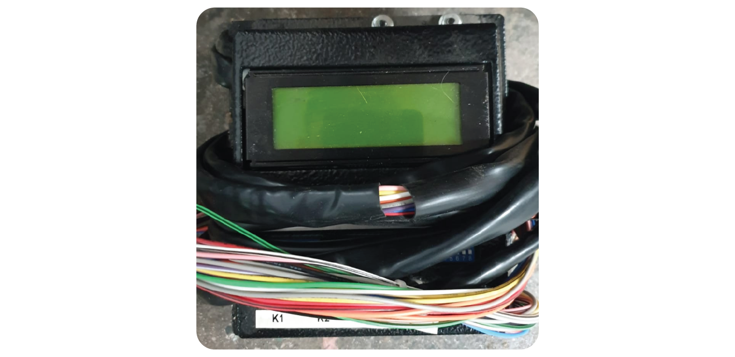
Step 2: Remove the 7 Segment Display credit display
Remove the connector connected to the credit display and cable tie it neatly with the existing wires like so:
Remove the 4 x screws of the credit display and remove it from the machine.
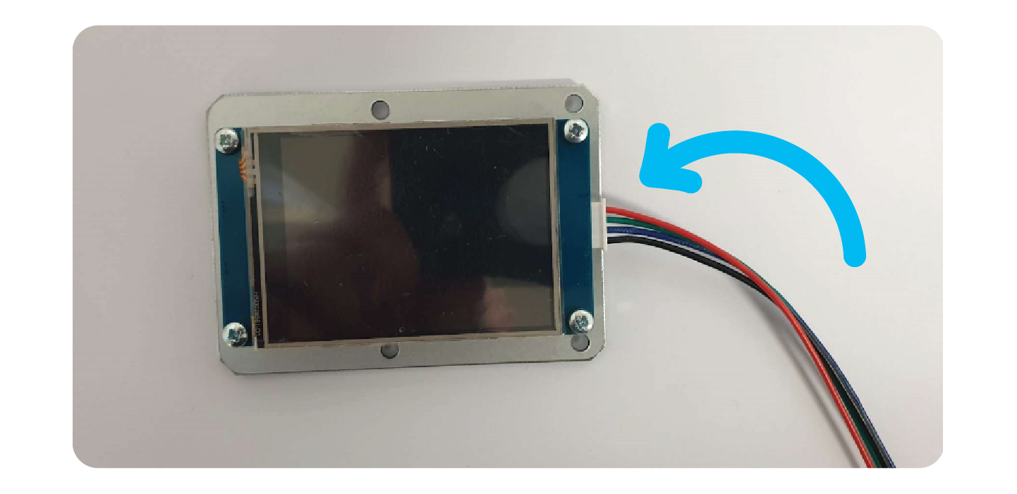
Step 3: Install the new credit display
Take the LCD Credit Display and the wiring for the LCD credit display.
Plug the connector into the LCD credit display:
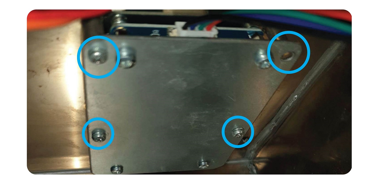
Screw the LCD display onto the machine using the existing screw mounts and the 4 holes in the bracket. The screen should be facing upwards and the connector towards you.
Step 4: Connect the Coin Mech and note reader
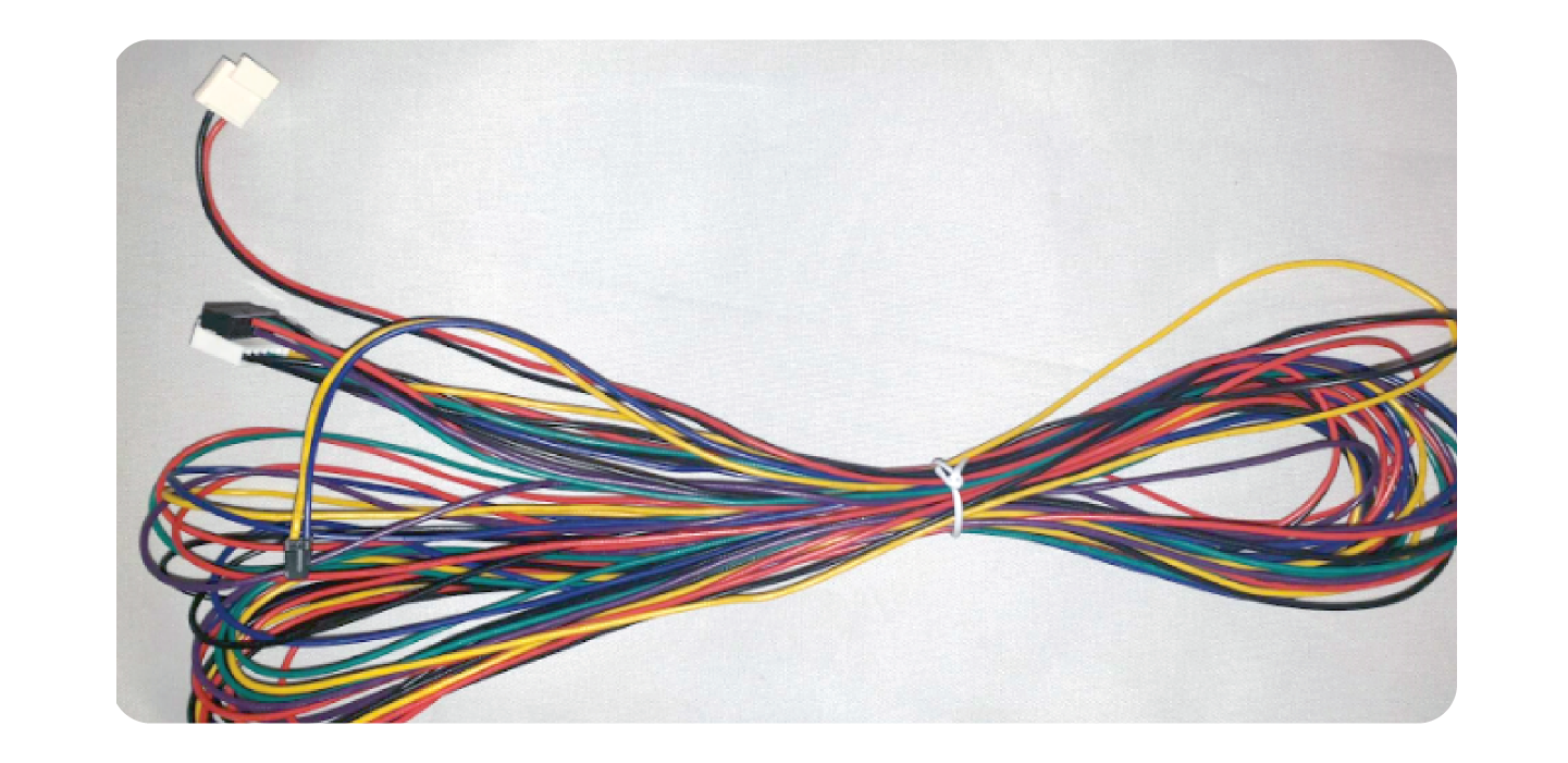
Take the new wiring loom for Coin Mech & Note reader and connect it to the coin mech and note reader.
Coin Mech
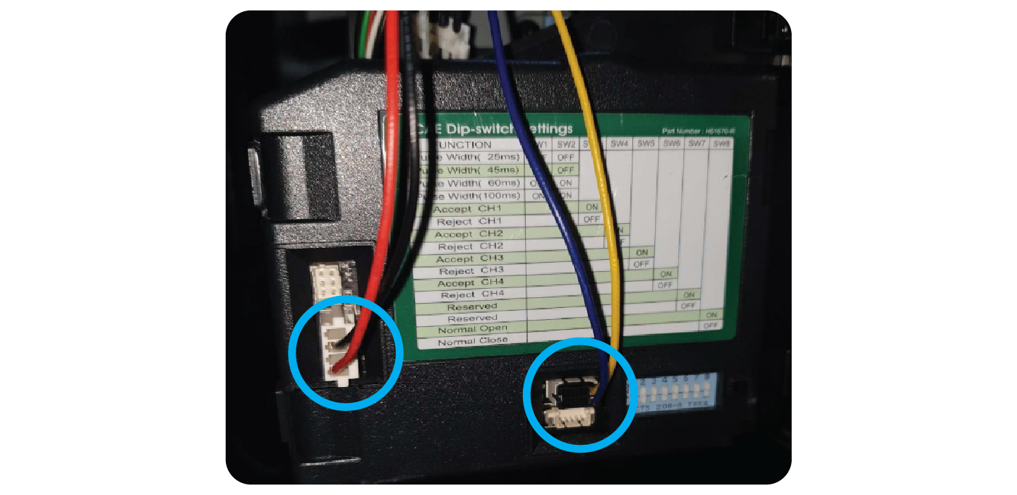
Take the Black and red wire connector, and the yellow and purple connector and connect them to the coin mech like so:
Note:
Some coin mechs have a different connector, if that is the case leave the existing wire in there and tie back the new red and black connector like so:
Note Reader:
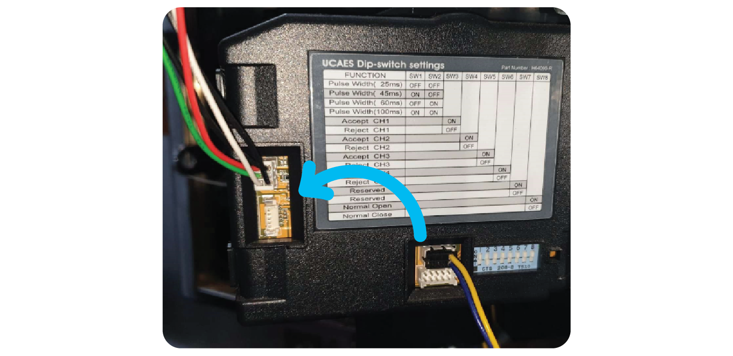
Plug the note reader connector into the side of the note reader. Once connected, secure it using the clip and screw that was golding the previous wire in place:
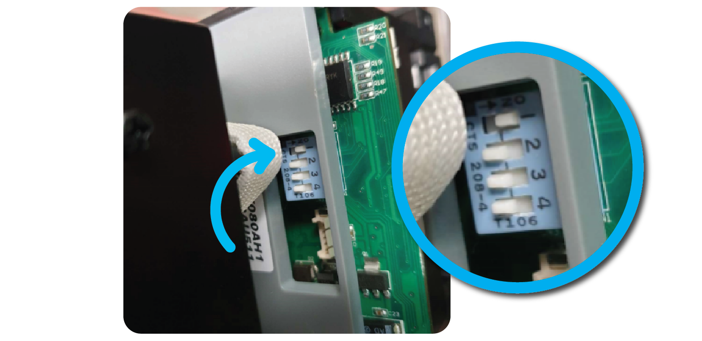
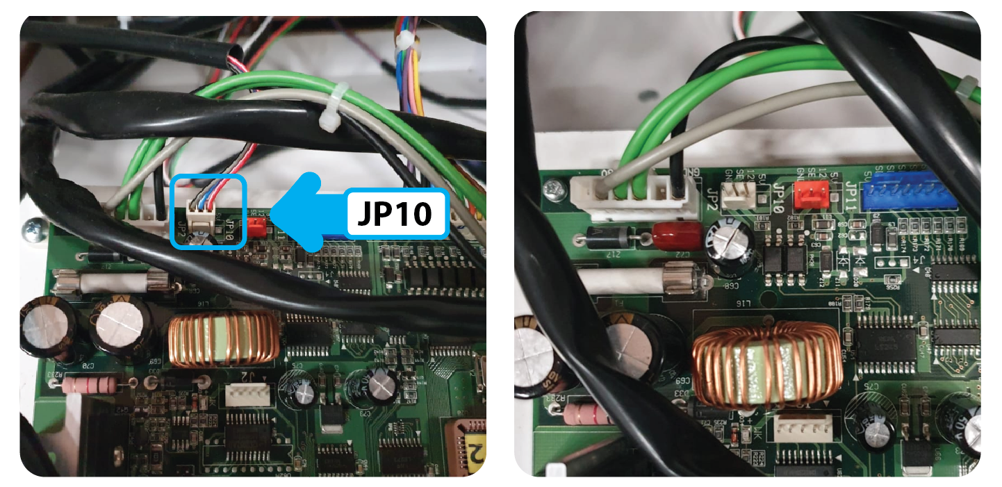
Once you have connected the wire, turn the note reader upside down and adjust the 4 Dip Switches, after you have changed them only 1 should be ON:
Attach the note reader to the machine, making sure it is firmly clipped onto the face plate.
Wiring:
It is important to tidy the new wiring, and neatly cable tie it to the existing wiring in the machine. Also include it inside the plastic cord protector that’s already in the machine:
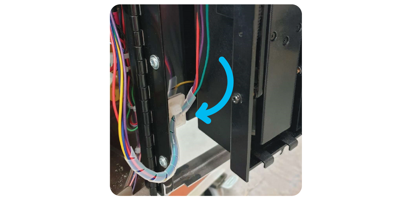
Once you have tidied the wiring, put it into the back of the machine for when you connect it to the new board in later steps.
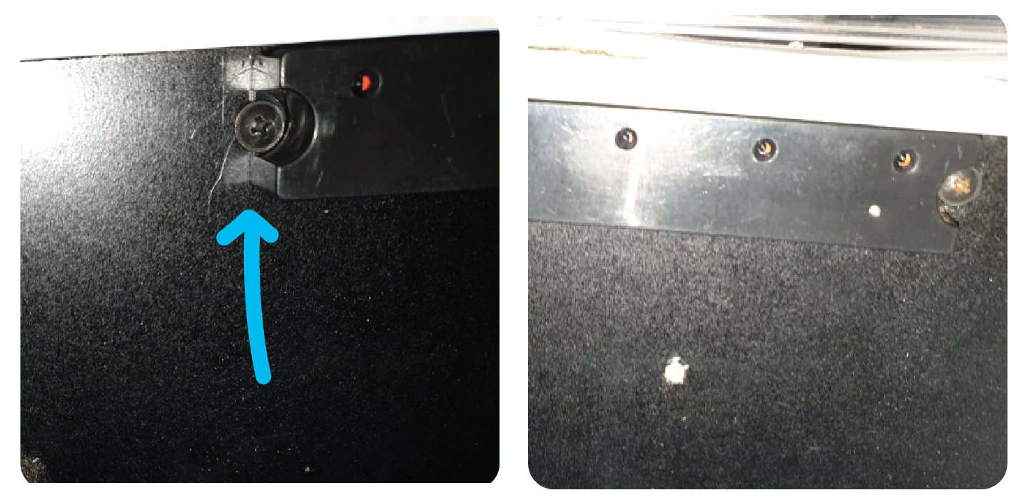
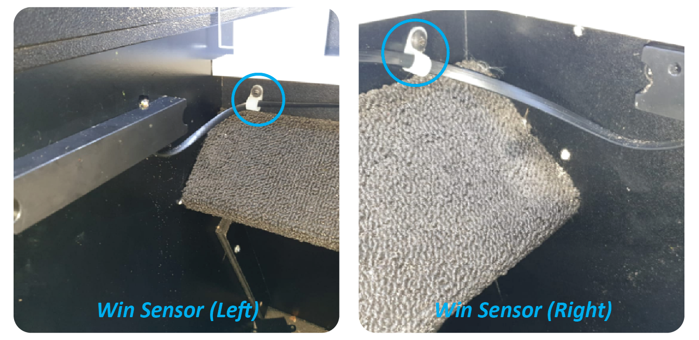
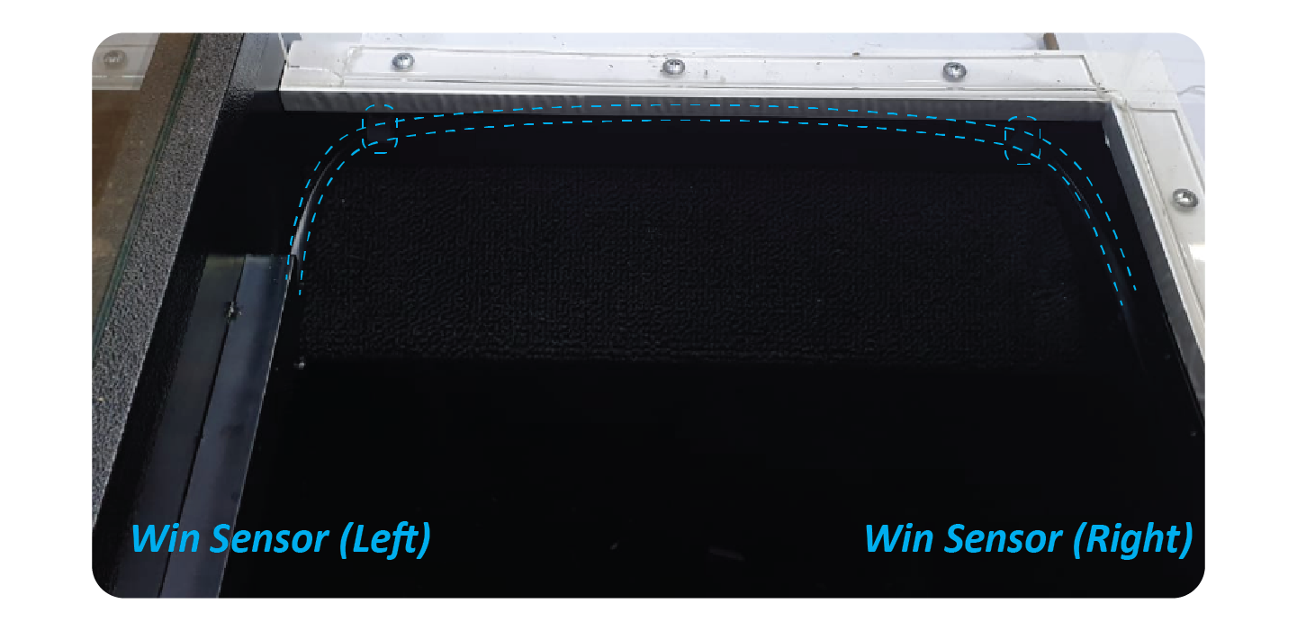
Step 5: Replace the Win Sensor:
Remove the old win sensor and cable.
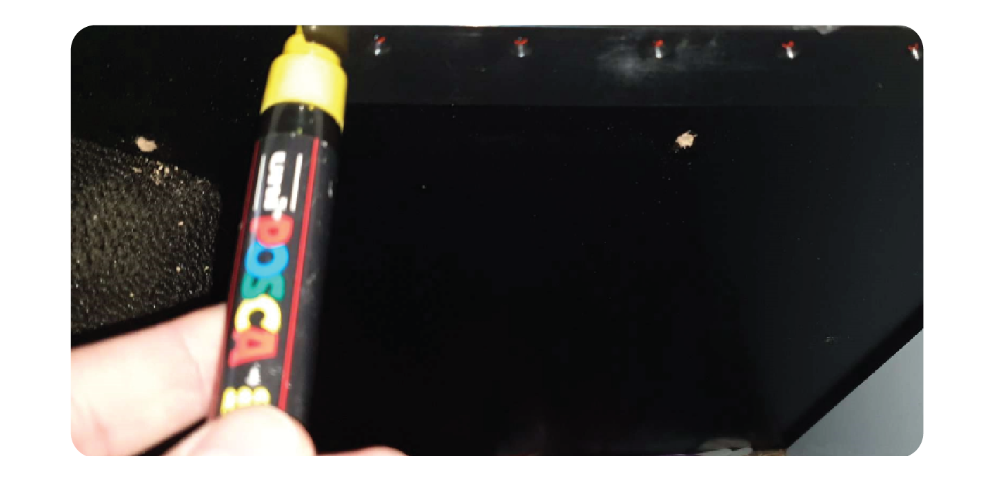
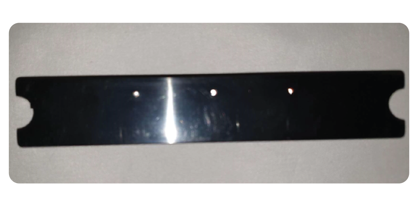
Take the new win sensor and a marker pen.
This side should take the RX Win sensor (the one with 5 holes).
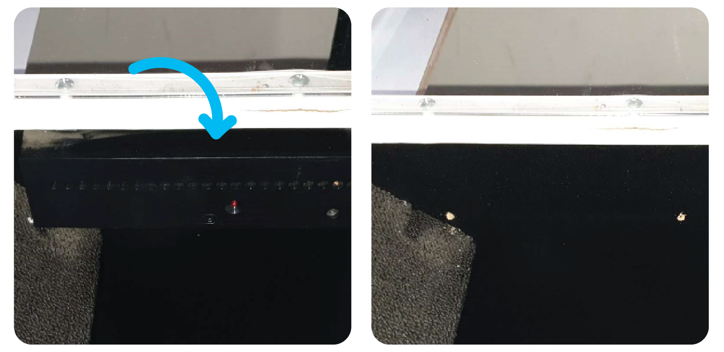
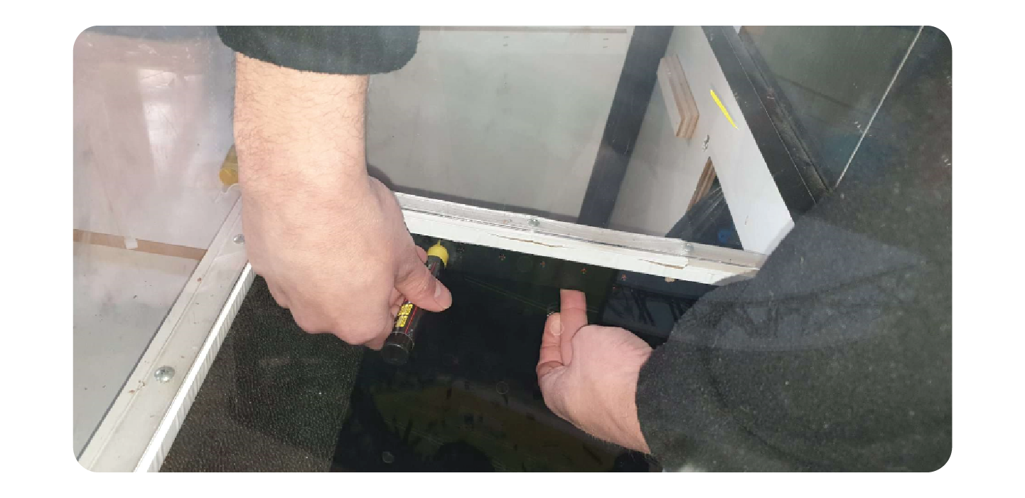
Place the win sensor directly in the middle of the prize chute. Line it up touching and parallel with the lip of the prize chut
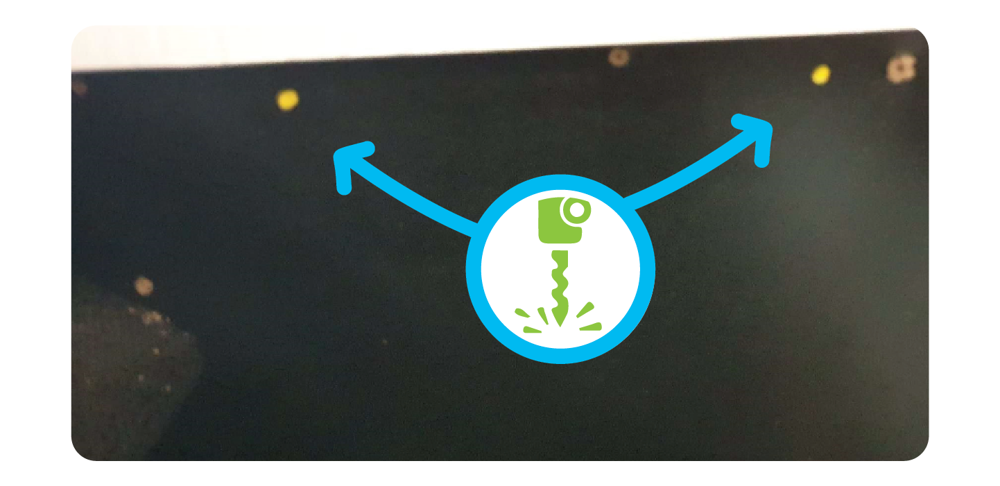
Take the marker pen and make a mark at either side of the sensor, where the grooves for screws are:
Drill a small hole where both of your marks are:
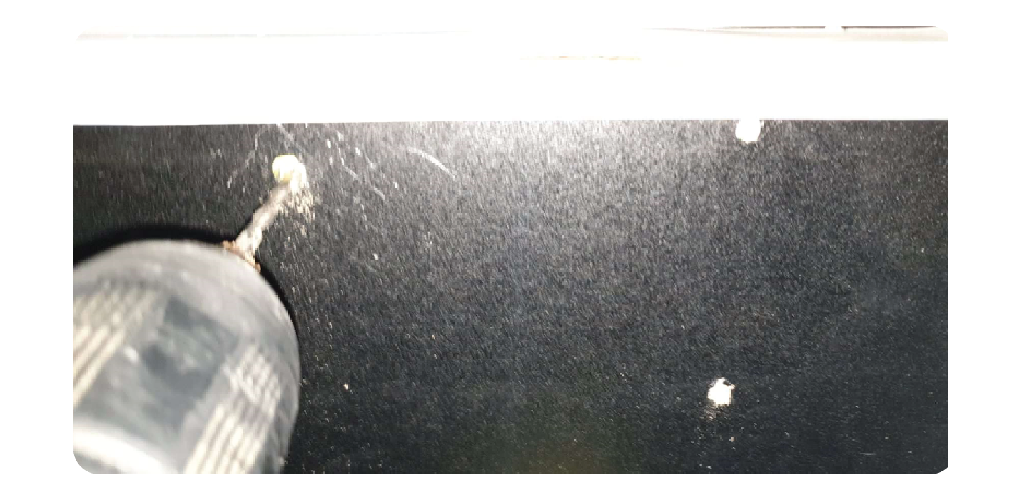
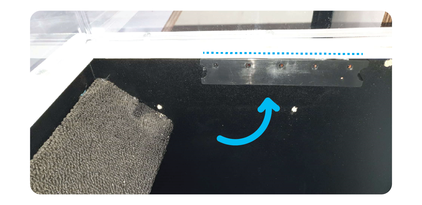
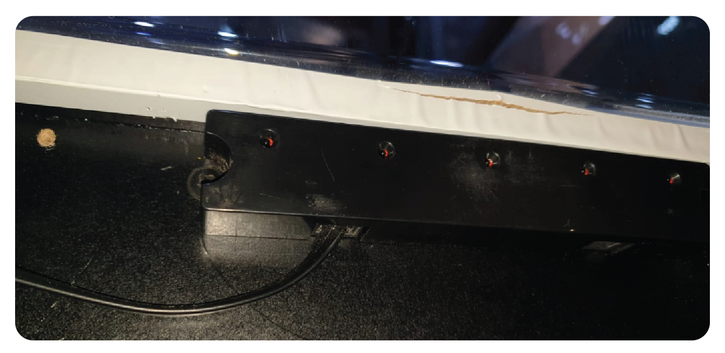
Using the screws provided and the holes you just drilled, mount the win sensor to the prize Chute:
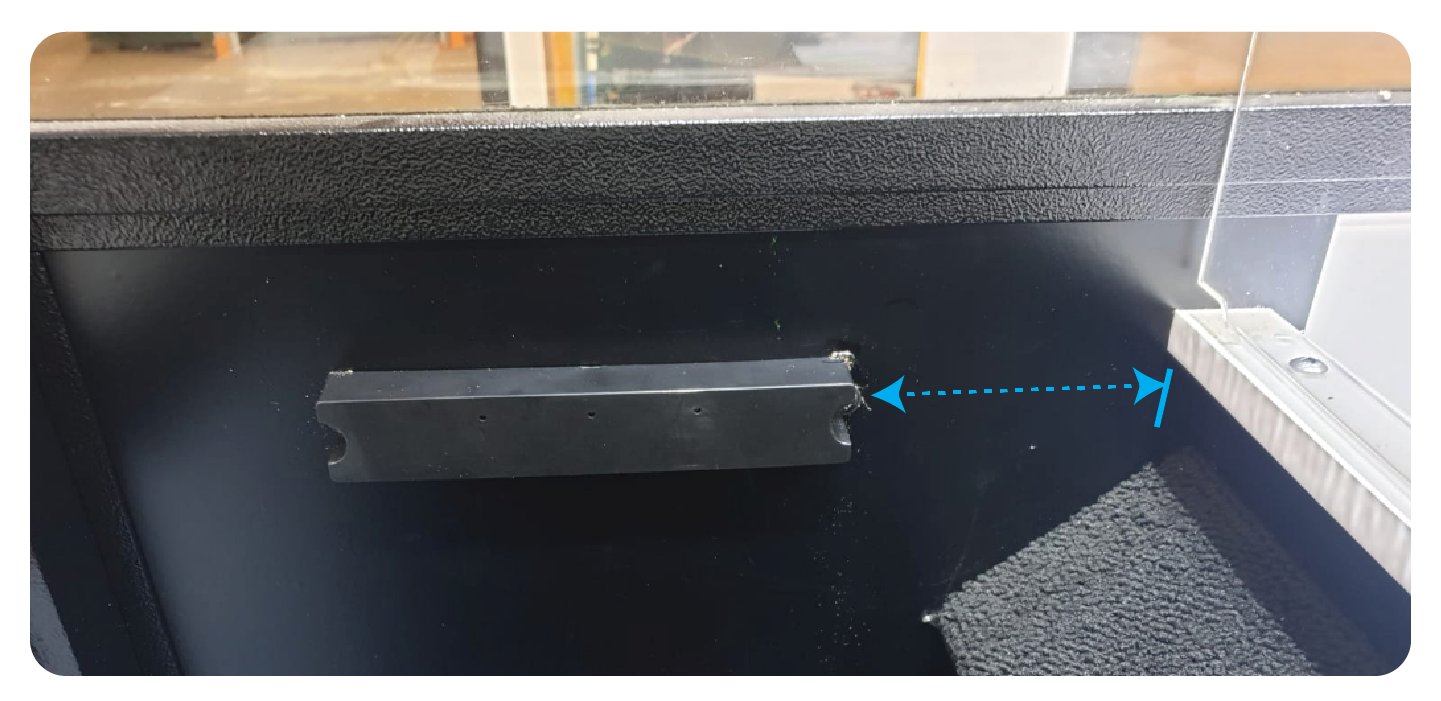
Mounting the Opposite Win Sensor.
Using the Opposite win sensor (The TX with only 3 small holes), install this directly on the opposite side of the prize sensor.
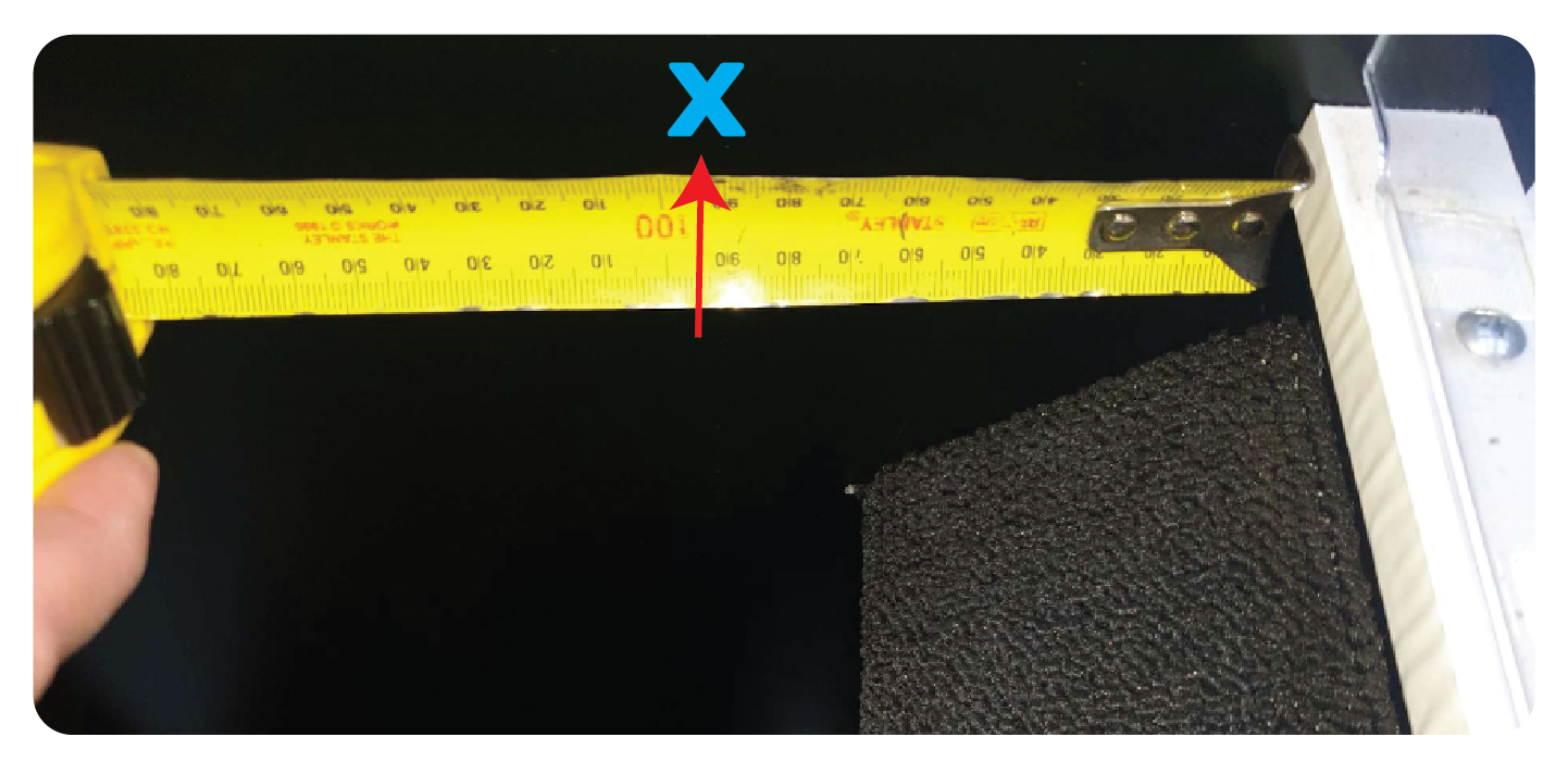
Measure the distance from the lip or the prize chutes lip to the first screw on the one you already installed.
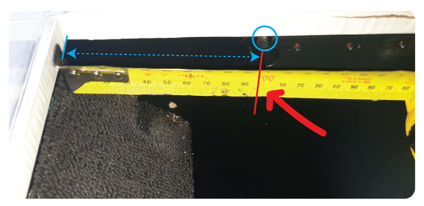
Do this on the opposite side for a starting point of where the win sensor should be installed. Mark the edge with a marker
As before, use a marker to mark the holes for the screws.
Drill a small hole (being careful not to drill all the way to the outside)
Then mount the win sensor using the screws provided.
Connecting the Win Sensor Wiring
Take the shorter (60cm) win sensor wiring and plug it into the win sensor like so:
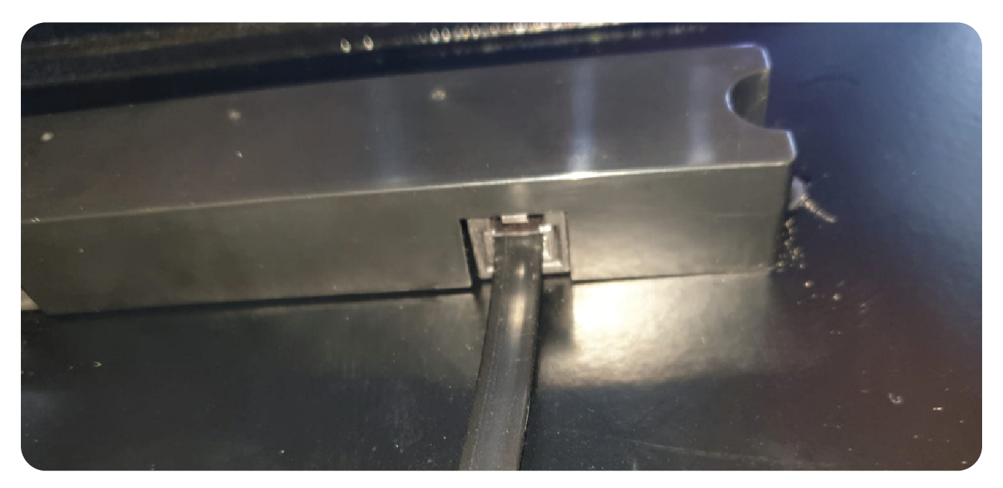
Plug the other side into the opposite sensor:
Using P Clips to secure them, tidy the wire under the lip of the prize chute:
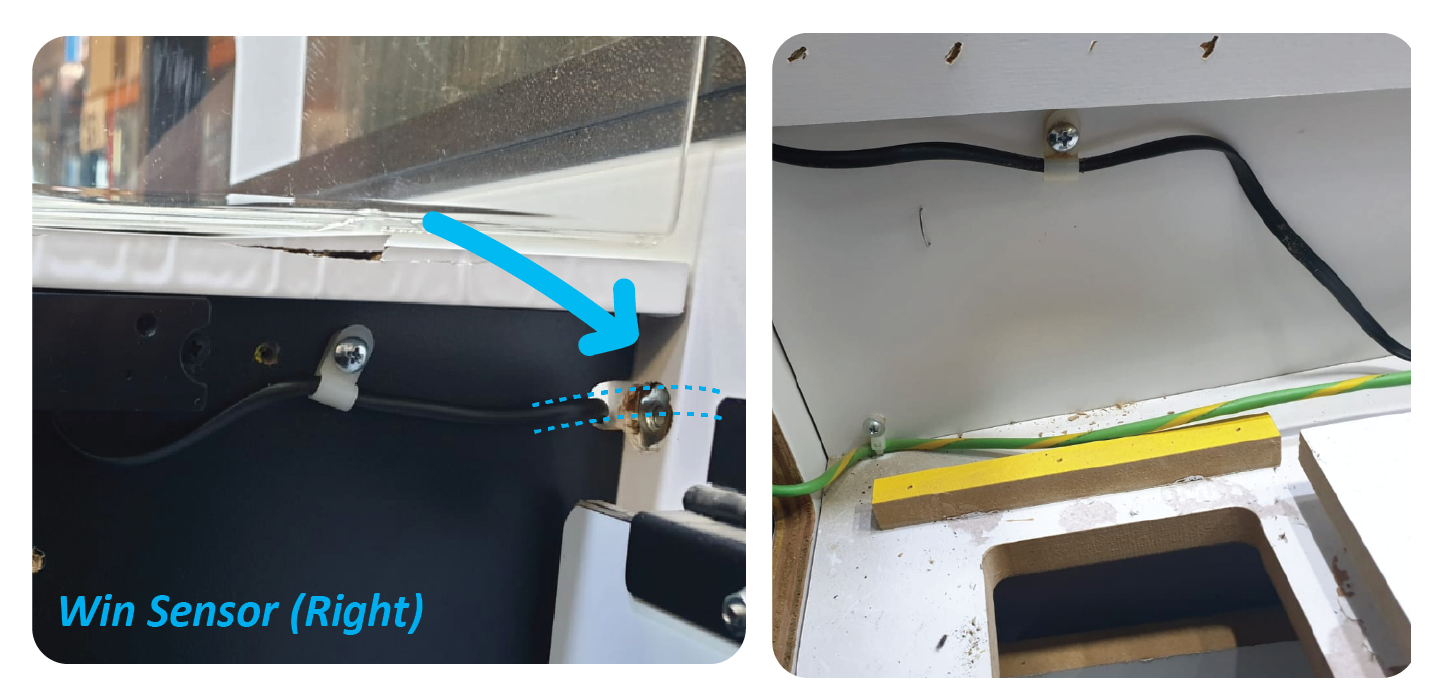
Add the longer wire to the Right hand side win sensor, and feed it through the gap to the back of the machine.
Secure it with P Clips:
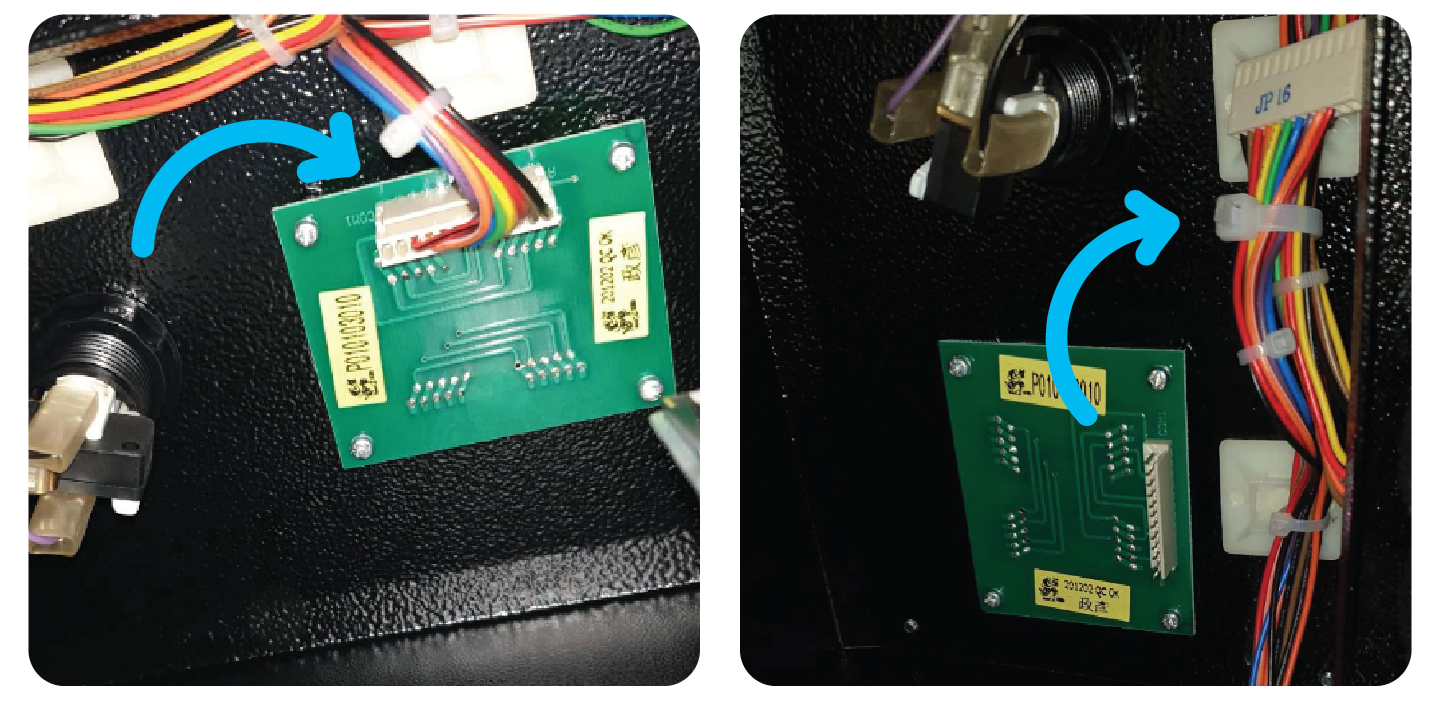
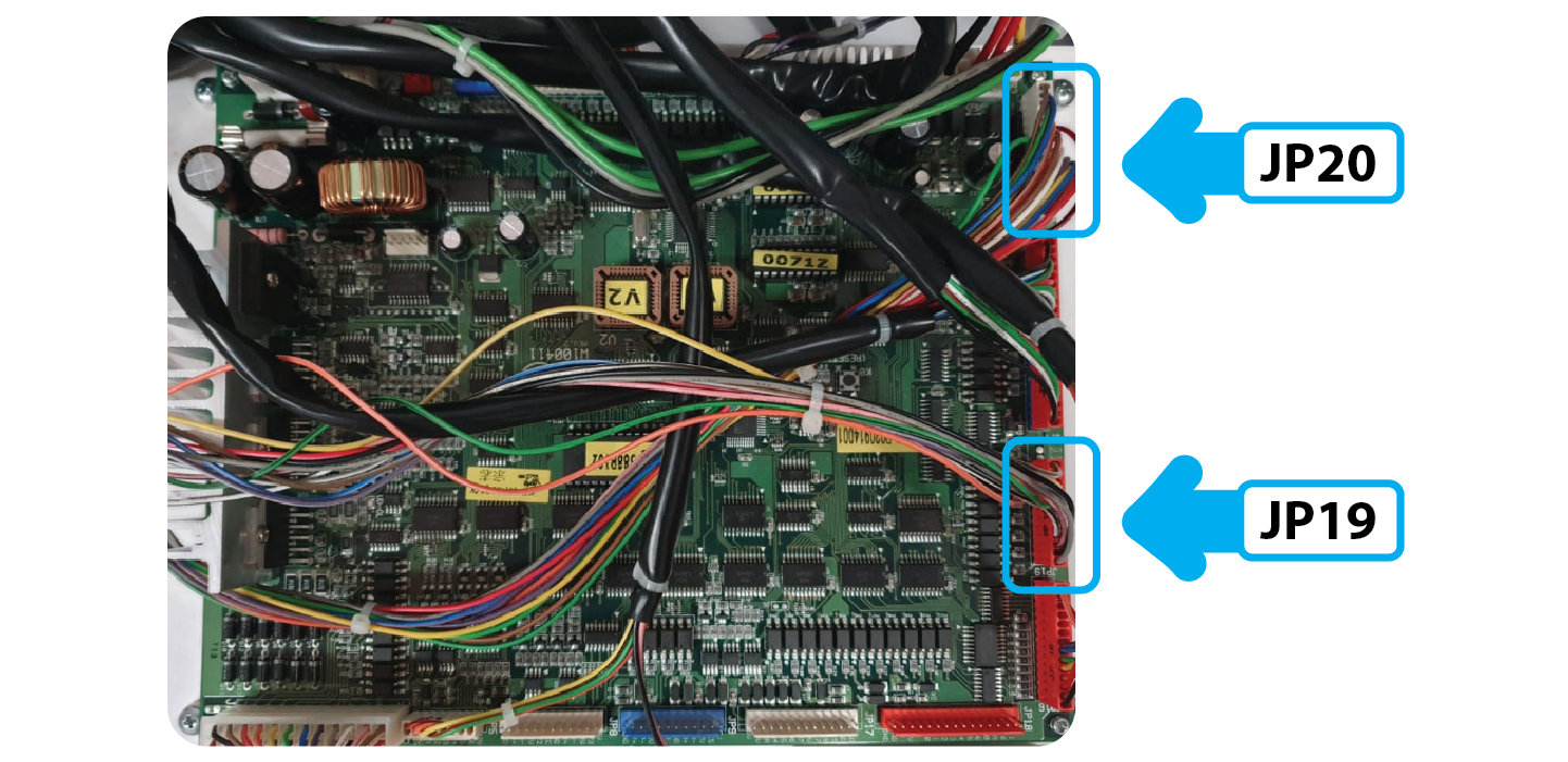
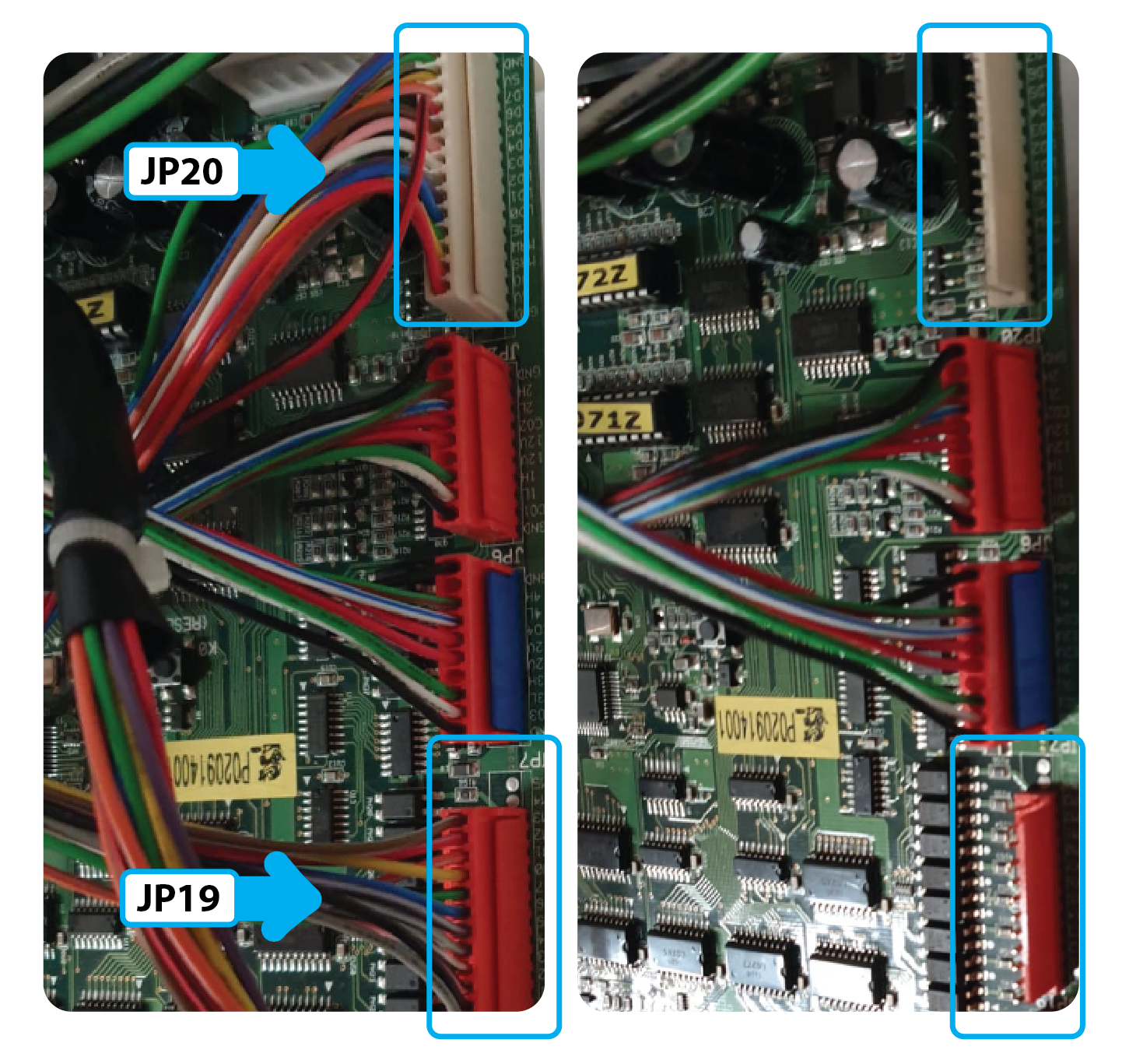
Step 6: Remove the LCM and Win Sensor wiring:
Unplug the connectors at JP19 & JP 20
Go to the front of the ,machine and remove the LCM. Take this with you it is no longer used.
Remove the old Win sensor wire from J10 and take this with you, it is no longer used:
Step 7:
Unplug the rest of the wires from the board and fuse board:
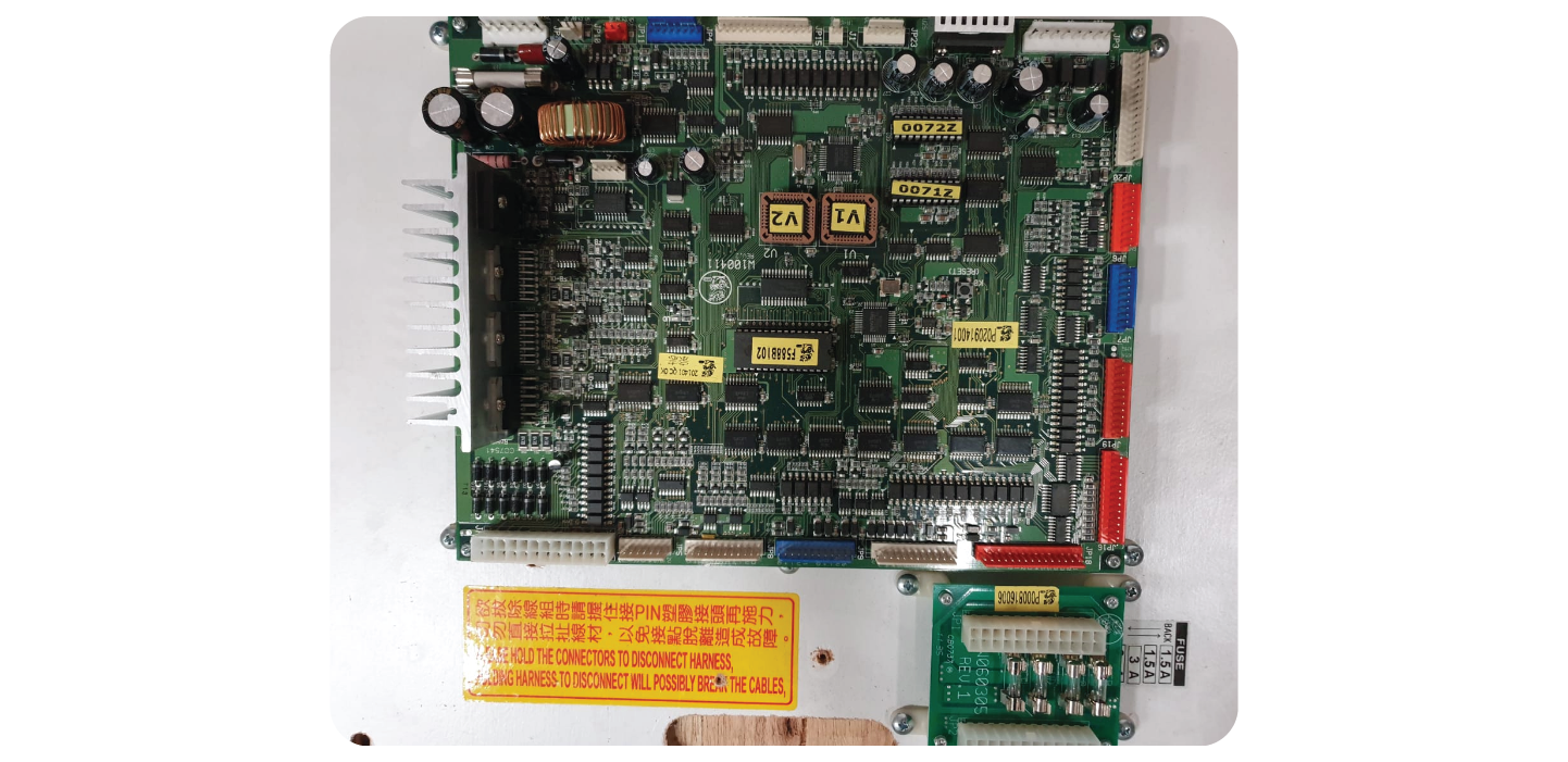
Remove the 2 boards:
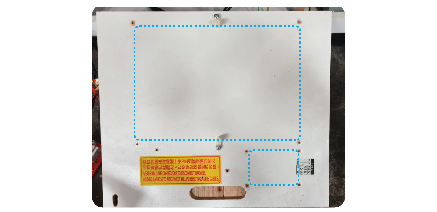
Install the 2 new boards, in the direction shown in the picture, with around 2cm gap between them both. Install them at the very back of the wooden board.
Take the fuses from the old fuse board and add them to the new one
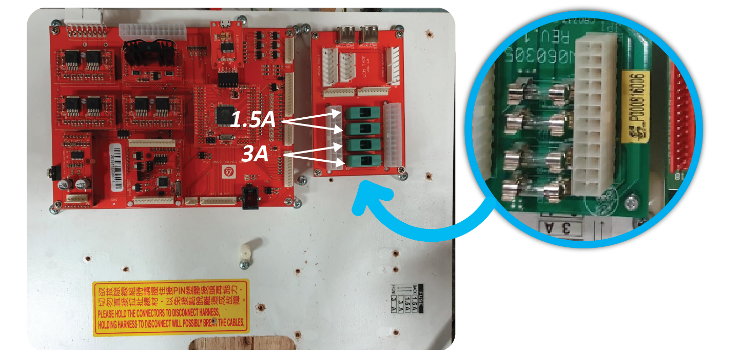
Plug the 2 leads coming from the power supply into the ‘POWER INPUT’ Connectors of the fuse board:
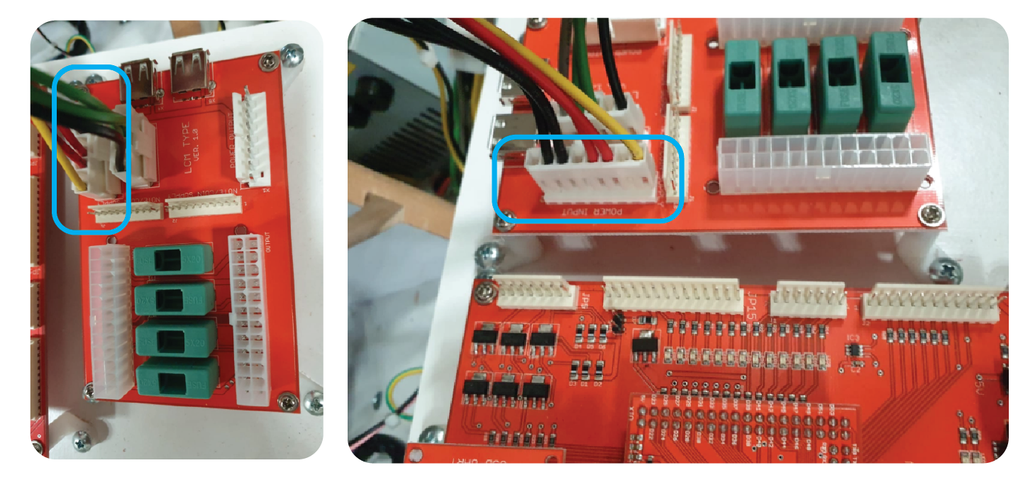
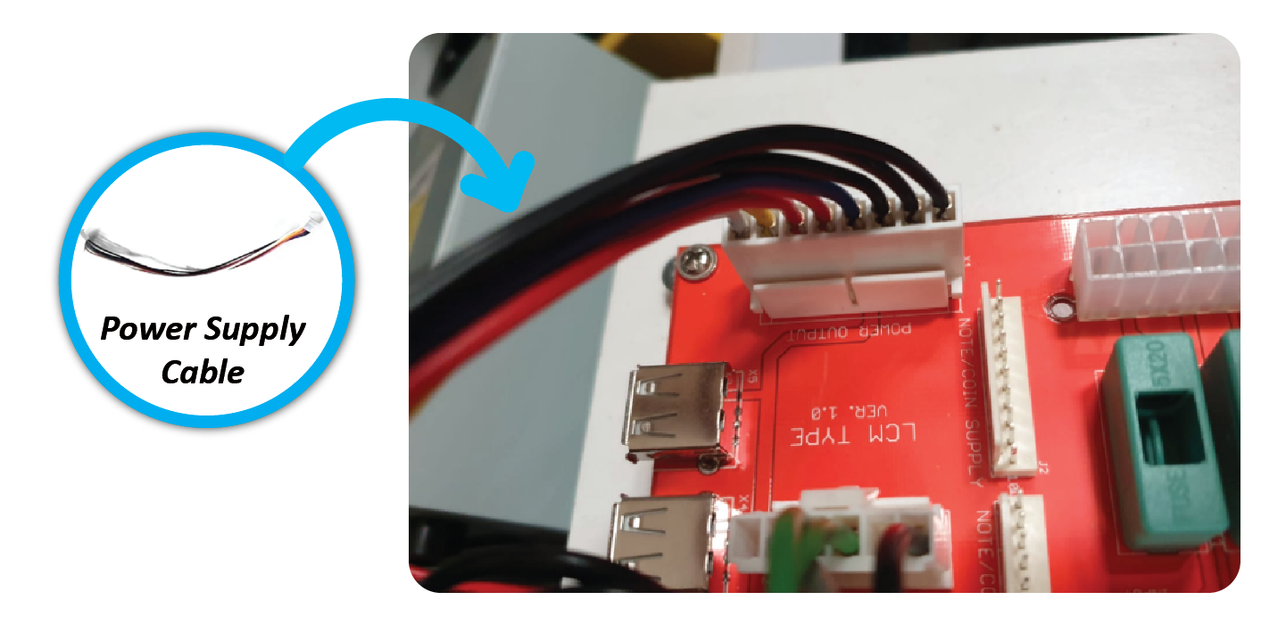
Add the Power Supply Cable to the ‘POWER OUTPUT’ connector on the right side of the fuse board:
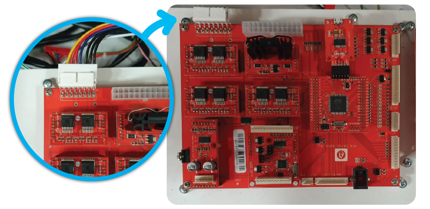
Add the other side to the ‘POWER INPUT’ connector at the top left of the Main Board:
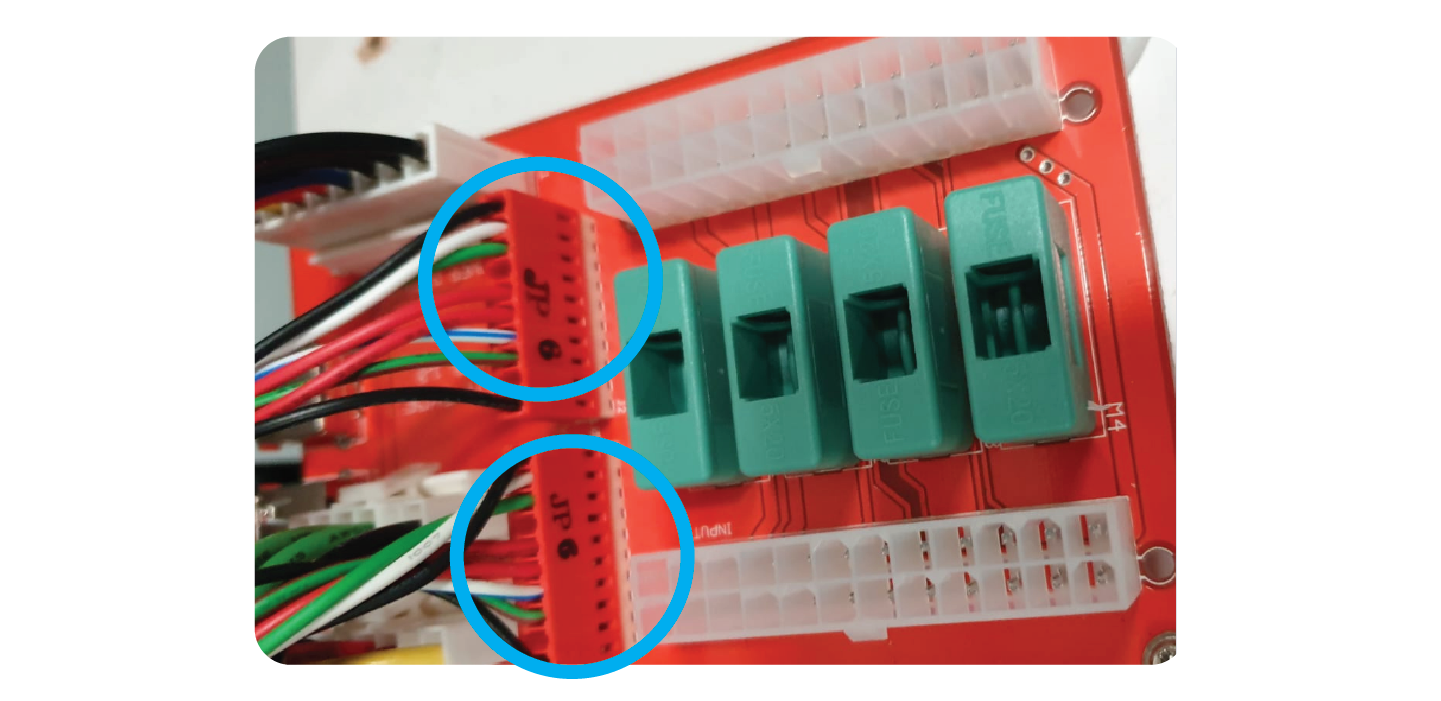
Add the 2 JP6 wires to the ports on the fuse board labelled ‘NOTE/BILL SUPPLY’
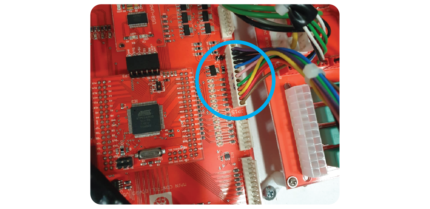
Add the ‘JP15’ lead to the connector on the right side of the main board labelled ‘JP15’:
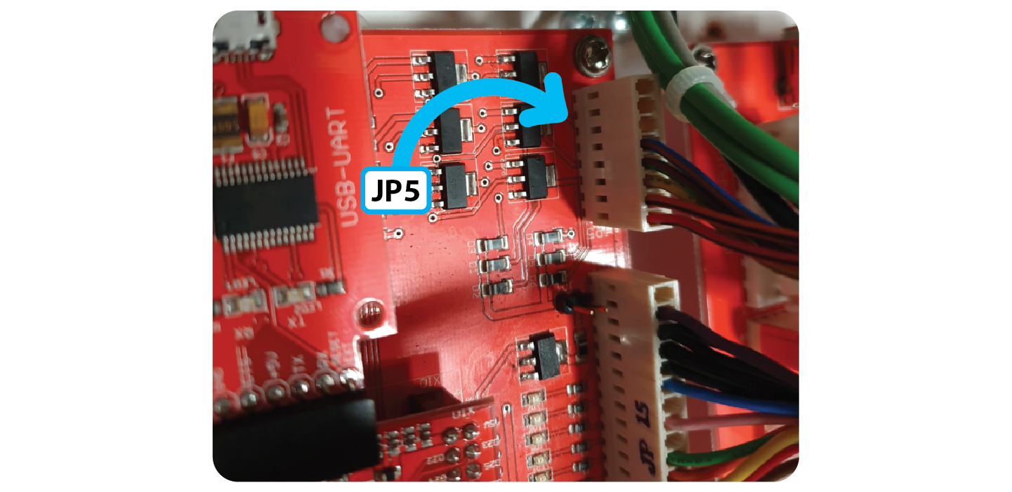
Add the JP5 Meter wire to the connector at the top right of the board labelled ‘JP5:
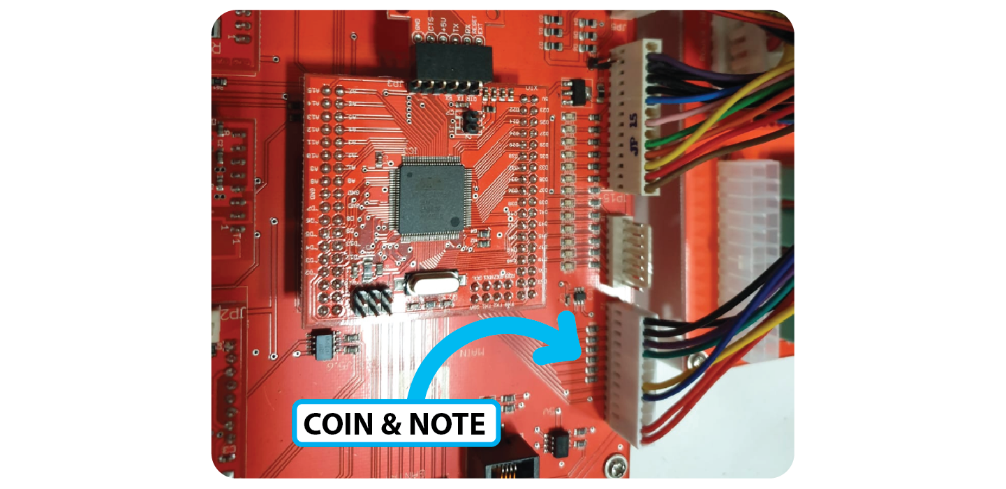
Add the new Coin & Note reader lead to the connector at the bottom right of the board:
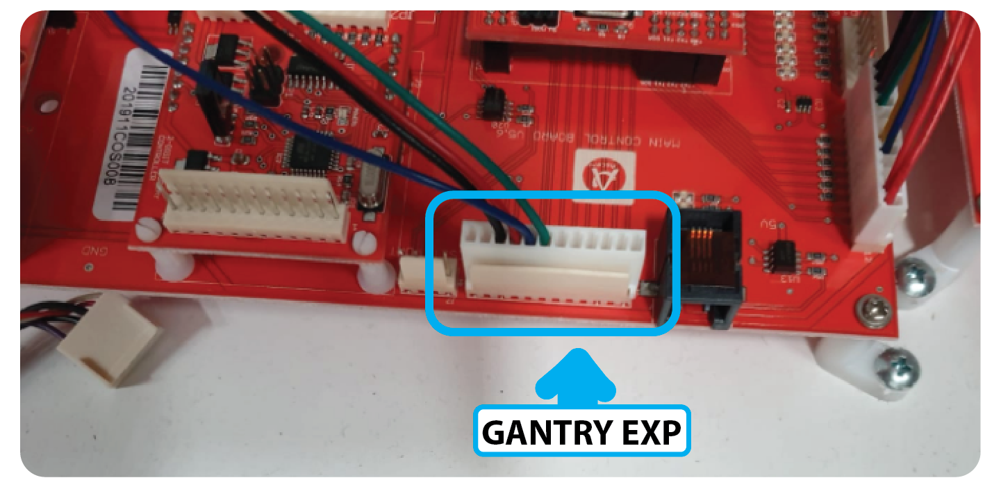
Add the new LCD screen wiring to the connector at the bottom right labelled ‘Gantry EXP’
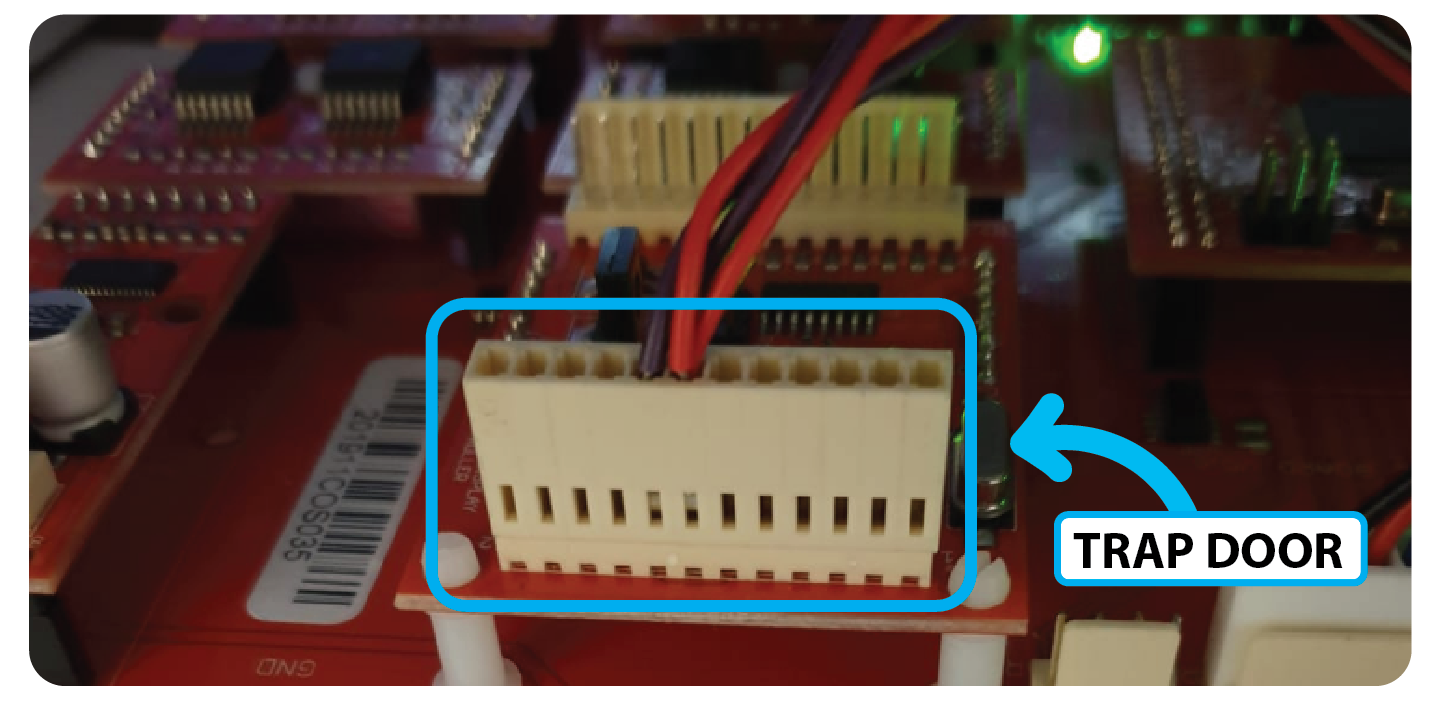
Add the Door lock cable (2 purple 2 red) to the 2 Digit Display Board:
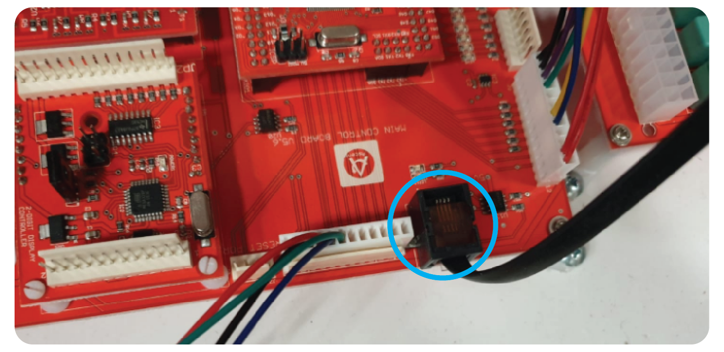
Plug the new Win Sensor Cable into the black RJ45 port at the bottom right:
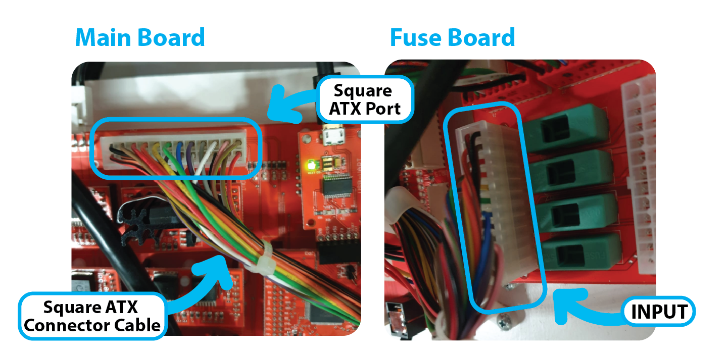
Add the Square ATX connector cable between the ‘INPUT’ Port of the Fuse board and the ATX port of the Main Board:
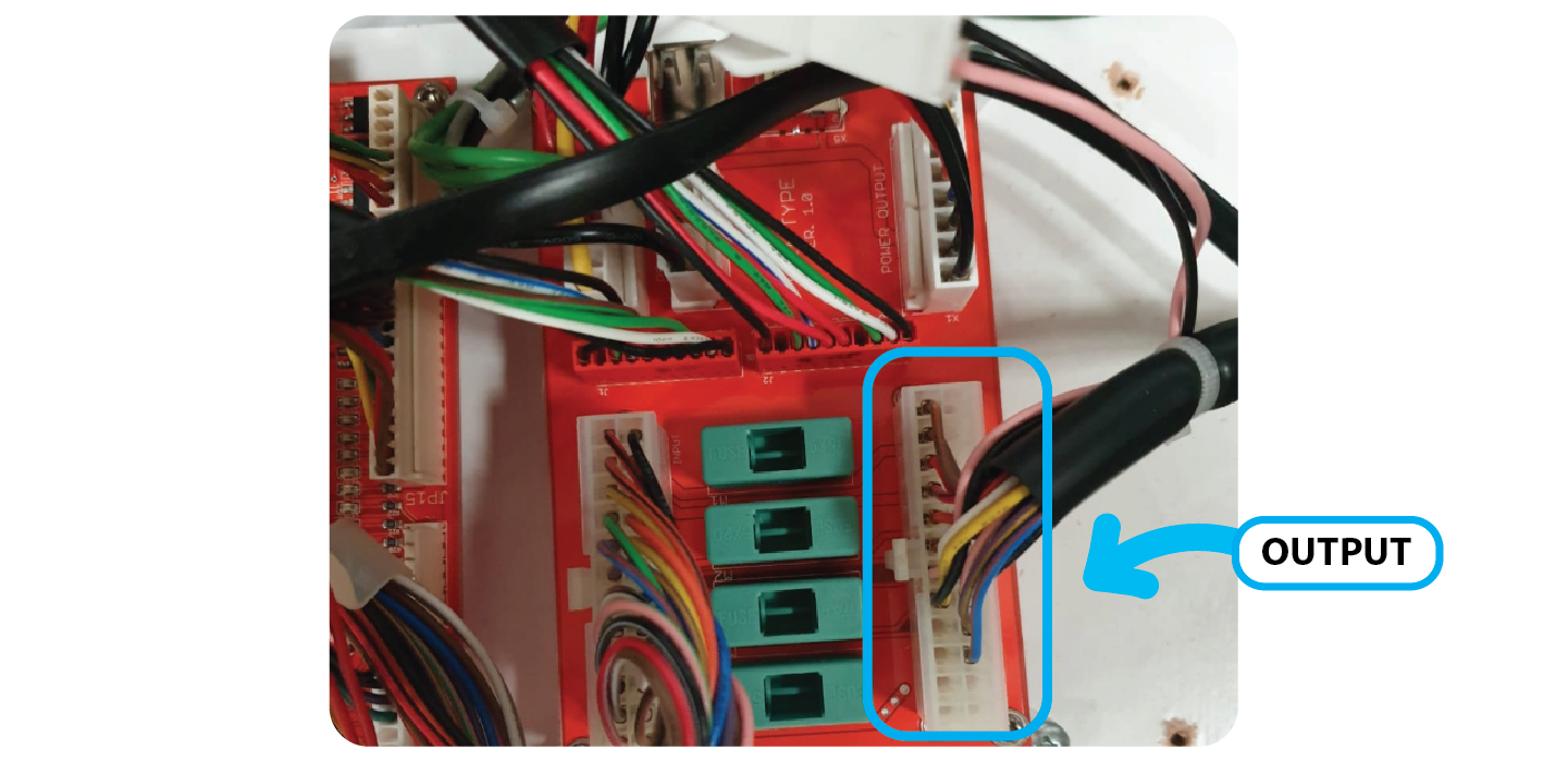
Add the other ATX connector that runs into the machine to the ‘OUTPUT’ port on the right hand side of the Fuse Board:
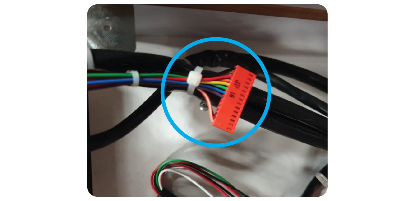
Tie back the JP 16 Cable as it’s no longer used:
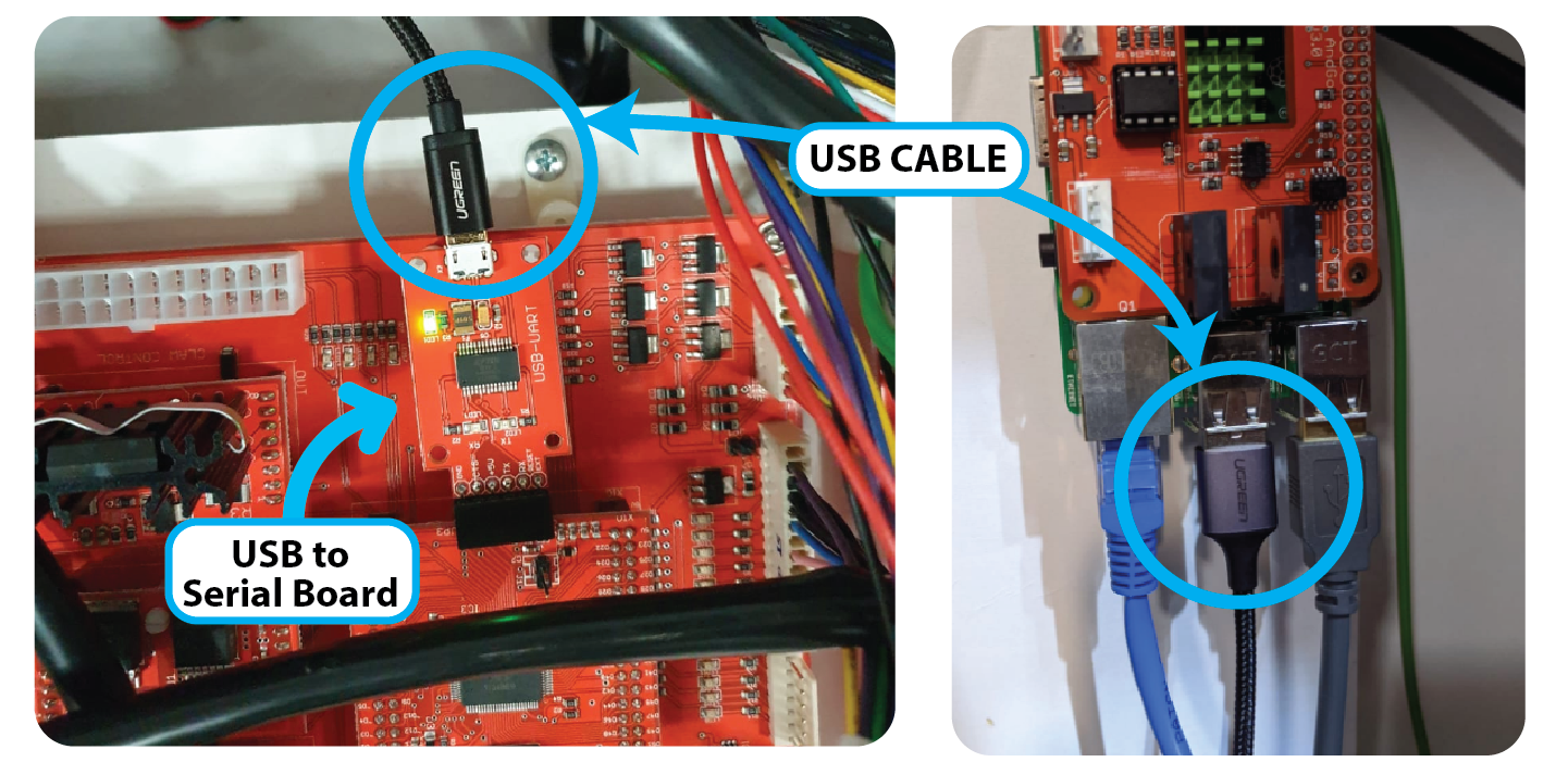
Add the Micro USB cable between the USB to serial board and the Raspberry pi:
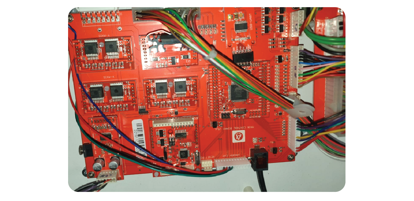
Once all wiring harness’ are installed, it should look like this:
Last Step: TEST
Contact Ariel/Randyll and have them confirm that everything is communicating on their end.
Then you will test:
- Coins
- Notes
- Card
- Win
- All Claw movements
- Prize Door Locks (Where Applicable)