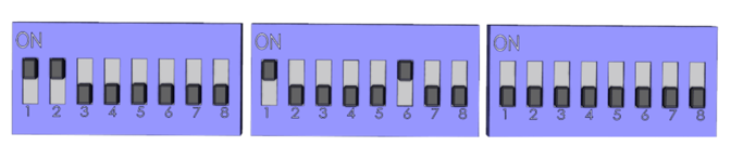
Step 1: Turn the Machine Off
1. Turn the machine off using the main power switch
Safety: Never open the LCM while the machine is powered on.
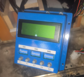
Step 2: Position the LCM for Access
1. Locate the LCM inside the machine console.
2. Carefully move or position the LCM so its back cover can be accessed.
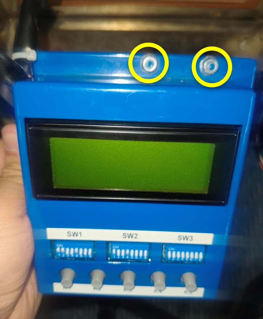
Step 3: Remove the Four Lock Nuts
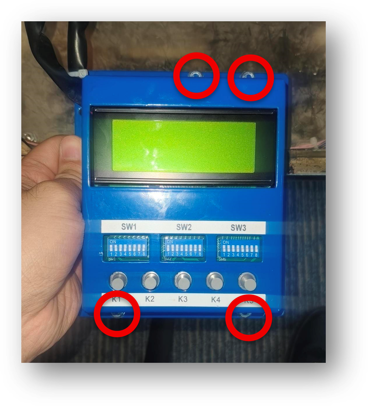
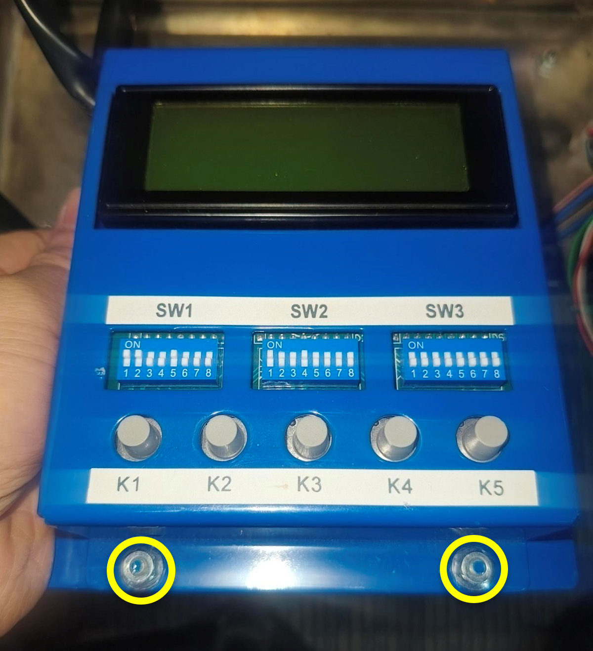
1. Locate the four lock nuts on the LCM. See photo below for reference.
Step 3: Remove the Four Lock Nuts
2. Using an 8 mm socket (preferred) or pliers if access is restricted, remove the four lock nuts securing the rear cover.
Step 4: Open the LCM Rear Cover
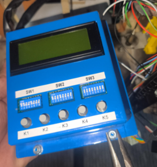
1. Carefully lift or pull the cover away from the LCM.
2. Do not pull the cover forcefully.
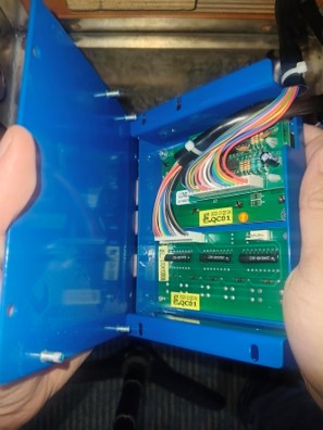
Step 4: Open the LCM Rear Cover
3. Identify the internal boards, the JP19 and JP20 connectors.
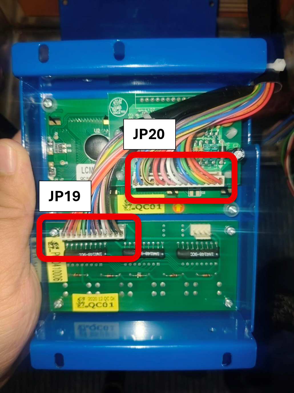
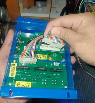
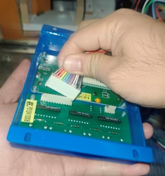
Step 5: Disconnect JP19 and JP20 Inside the LCM
1. Locate JP19 and JP20 inside the LCM.
2. Confirm the connector label before disconnecting it.
3. Pull it straight out.
Step 6: Remove the Existing Board
1. Identify the existing button board inside the LCM.
2. Check the position and orientation of the board.
3. Locate the four screws securing the button board.
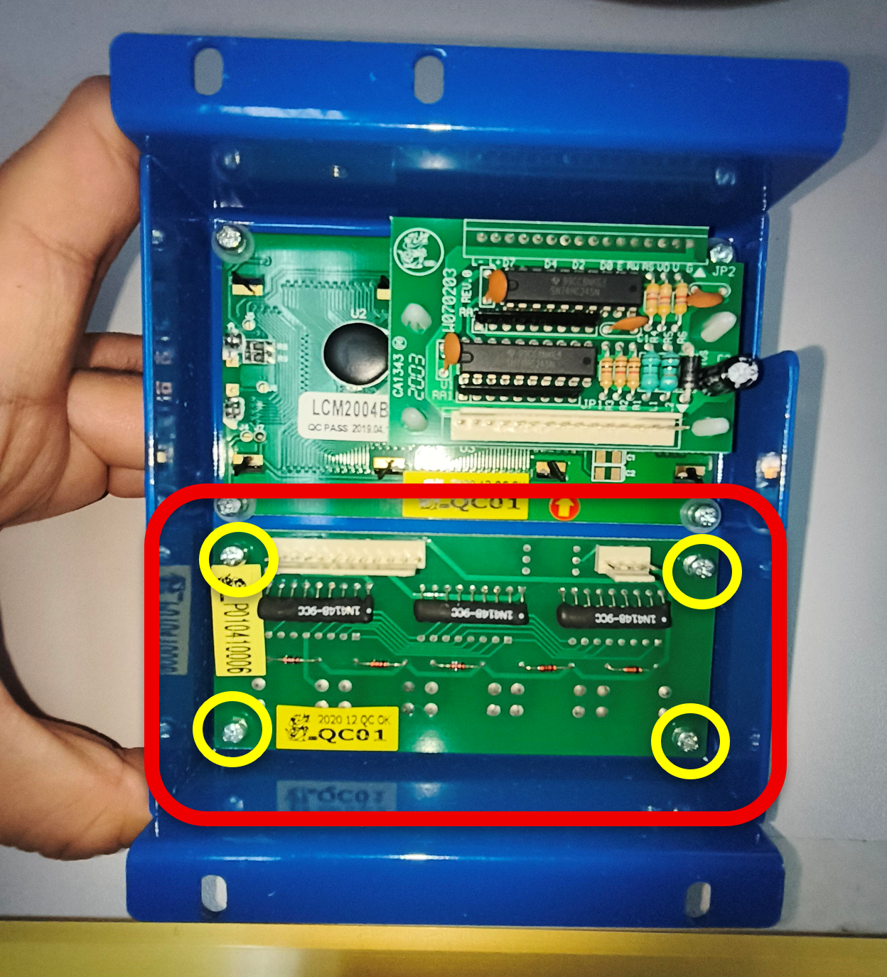
Step 6: Remove the Existing Board
4. Remove the four Phillips screws securing the button board.
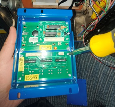
Step 6: Remove the Existing Board
5. Lift the button board from the holder.
6. Label the defective board for inspection or disposal.
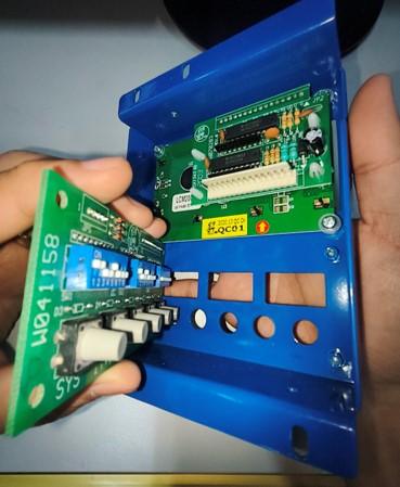
Step 7: Inspect the Replacement Board
Before installation, confirm:
• The board is not cracked, bent, or scratched.
• Connector pins are straight and clean.
• Each button switch moves or clicks when gently pressed.
• There is no dirt, moisture, corrosion, or visible damage.
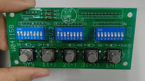
Step 8: Install the New Button Board
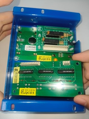
1. Position the new button board in the same orientation as the original.
Step 8: Install the New Button Board
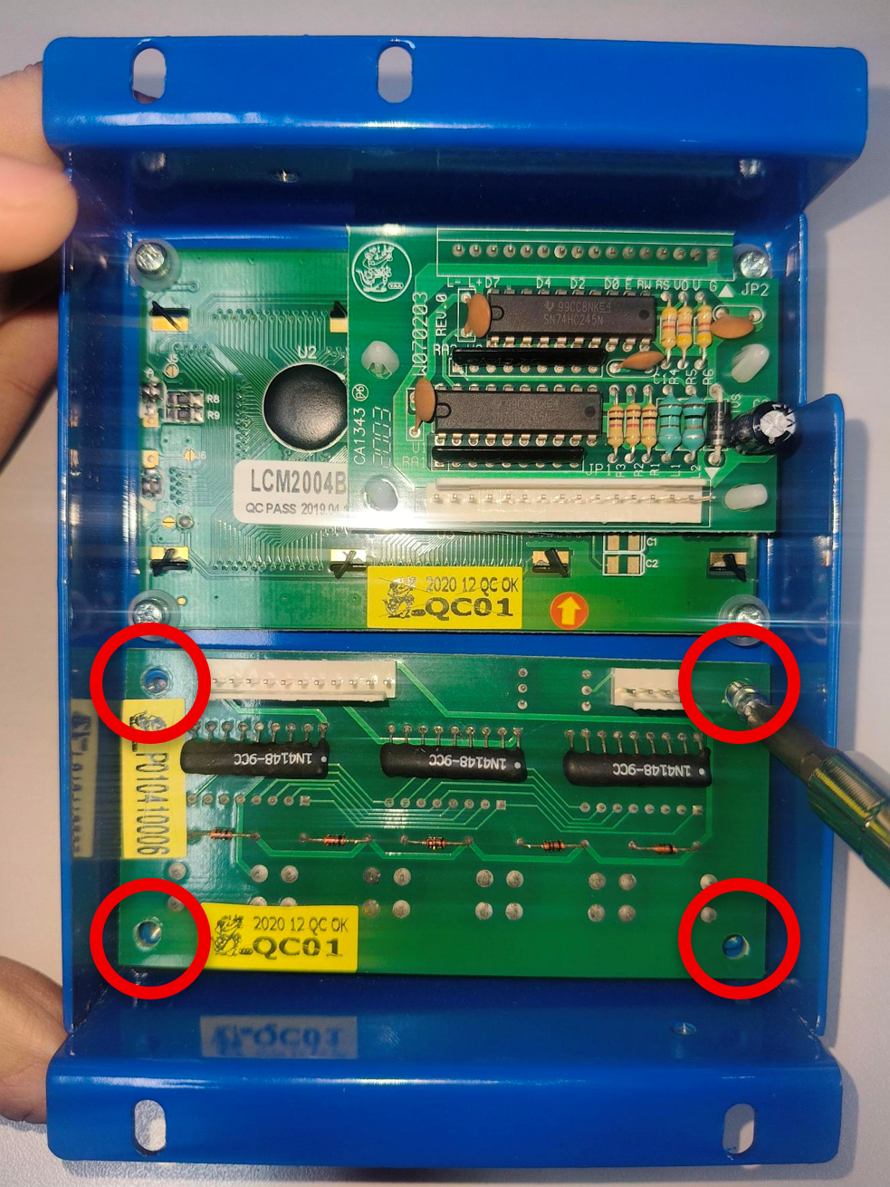
2. Align all four screw holes and ensure that the board is mounted flat into the case.
3. Install and tighten the four Philip screws evenly.
Step 9: Verify Button Movement
1. Press each external LCM button.
2. Confirm every button moves freely and returns normally.
3. Ensure the board does not shift during operation.
Step 10: Reconnect JP19 and JP20
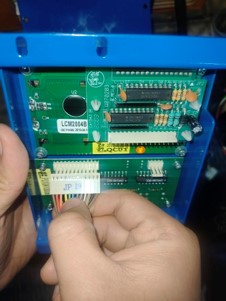
1. Locate JP19 and confirm the connector orientation.
2. Align the connector with the correct socket.
Step 10: Reconnect JP19 and JP20
3. Push it straight into the socket using gentle and even pressure.
4. Confirm that it is fully seated.
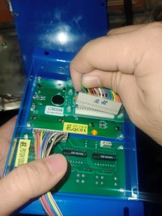
5. Locate JP20 and confirm the connector orientation.
6. Align the connector with the correct socket.
7. Push it straight into position using gentle and even pressure.
8. Confirm that it is fully seated.
Step 11: Arrange the Cables Correctly
1. Route JP19, JP20, and the other cables through the correct side opening of the LCM.
2. Follow the original cable routing shown in the reference photo.
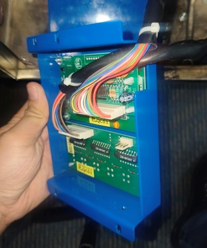
Step 12: Reinstall the LCM Back Cover
1. Position the back cover over the LCM in the correct direction.
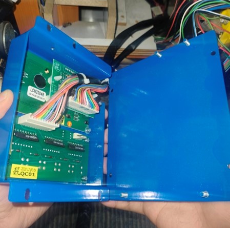
Step 12: Reinstall the LCM Back Cover
2. Check that no cable is trapped between the cover and the LCM housing.
3. Align the four mounting points.
4. Hold the cover securely while installing the lock nuts.
Step 13: Reinstall the Four Lock Nuts
1. Install four lock nuts.
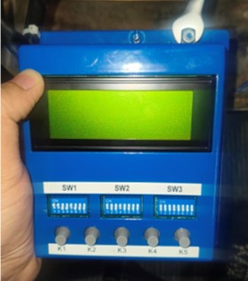
Step 13: Reinstall the Four Lock Nuts
2. Check that the back cover is evenly positioned.
3. Stop when the nuts are secure.
4. Confirm DIP Switches
For Large, Jumbo and Iron Claw machine Dip Switch Settings. (Click the image)
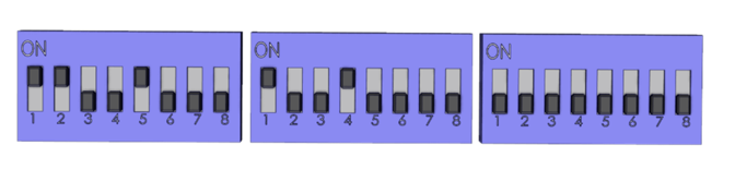
For Maxi Claw Machine Dip Switch Settings. (Click the image)