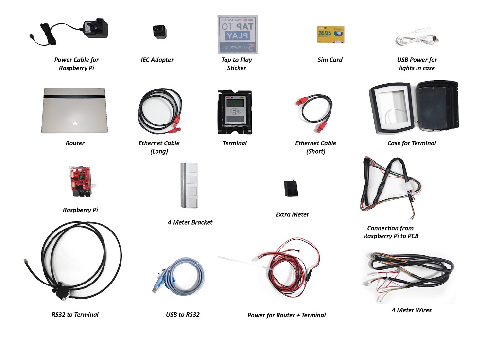
Step 1:
Open up the back fo the machine
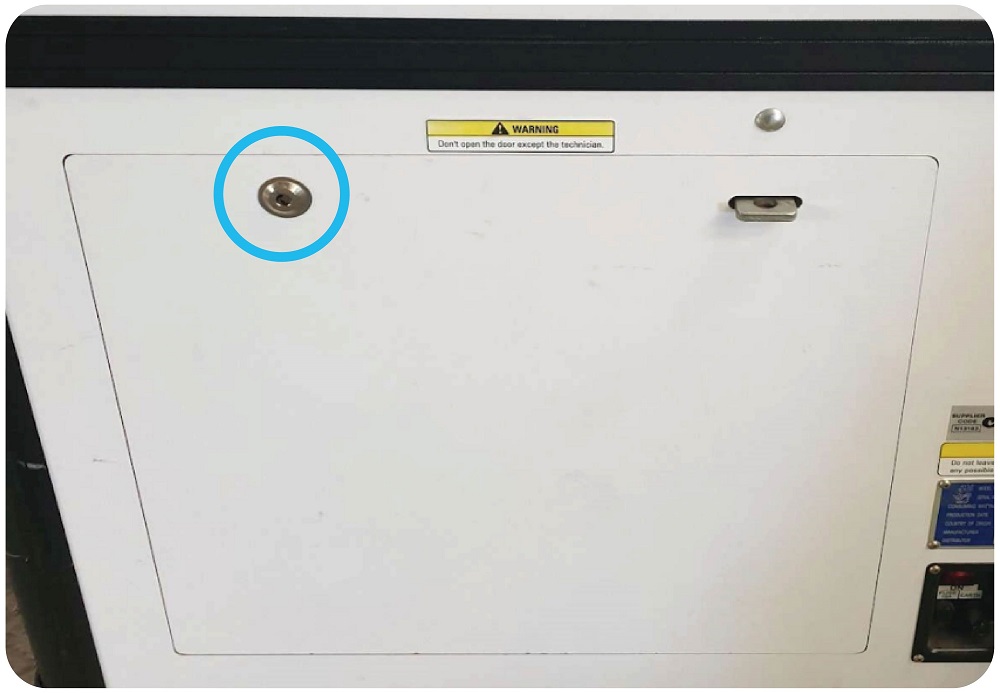
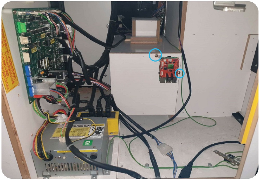
Step 2: Mounting the Raspberry Pi
Take the Raspberry Pi, Cordless Drill with 3mm Drill bit, 2 x wood screws and Philips screwdriver.
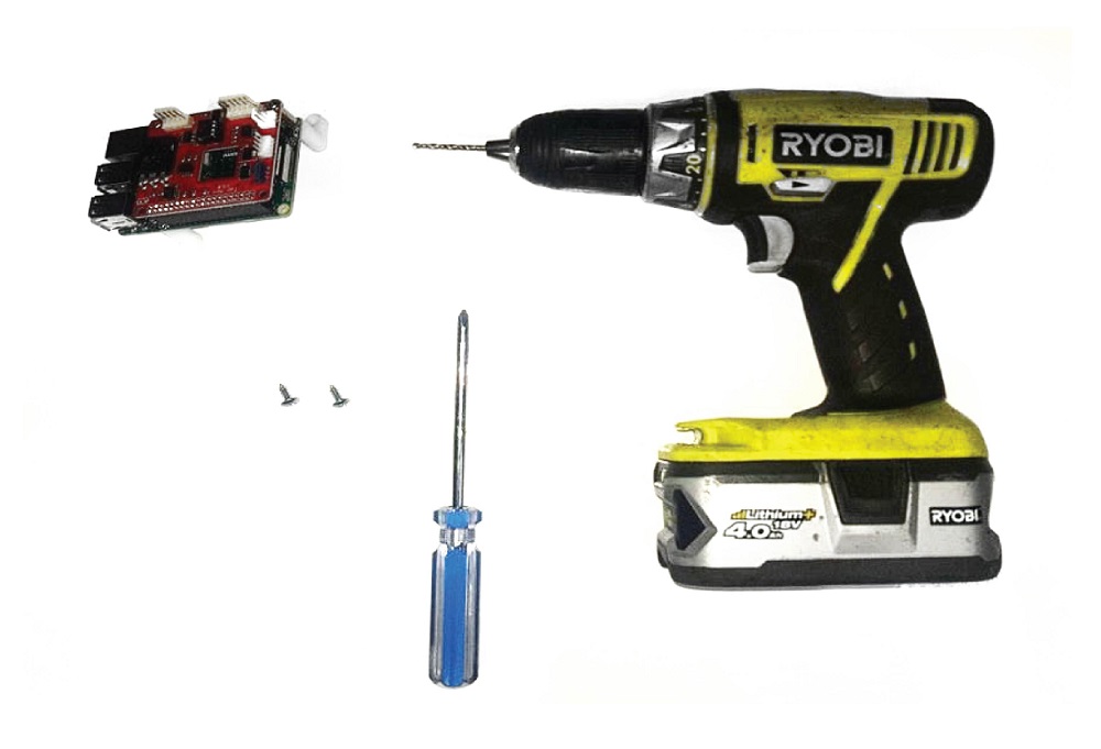
Using the cordless drill, make 2 holes in the back of the surround for the cashbox. One for each of the feet on the raspberry Pi.
Step 3: Plug in the Raspberry Pi power supply
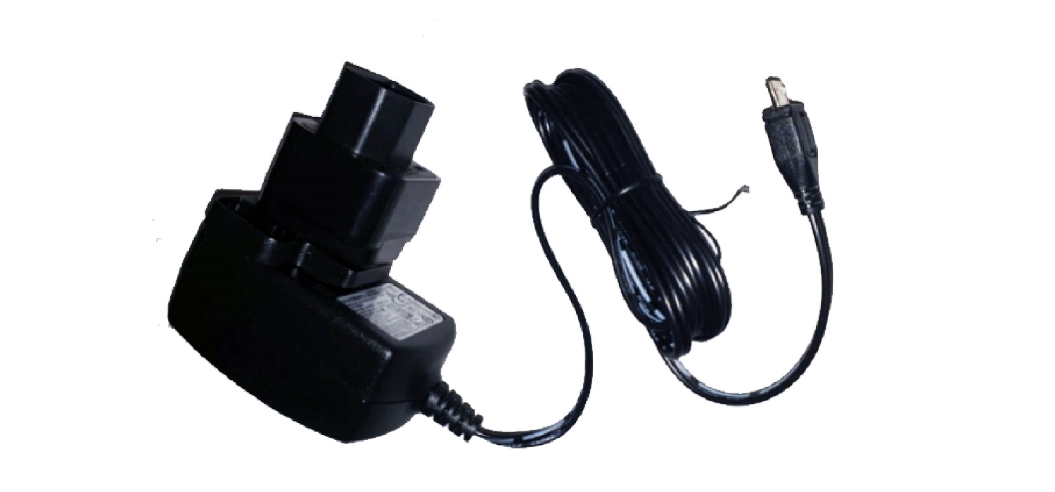
Take the Raspberry Pi Power supply and the IEC adapter.
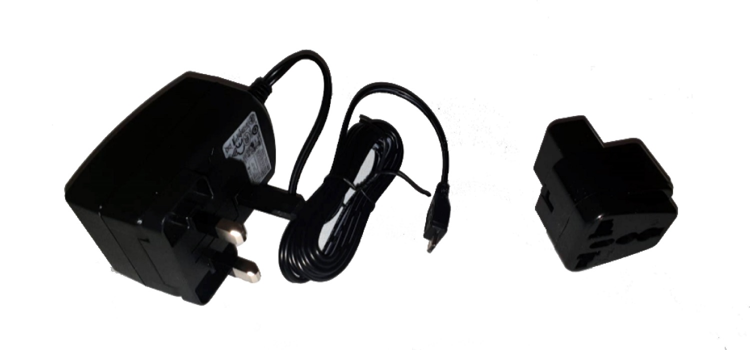
Put the plug into the IEC adapter:
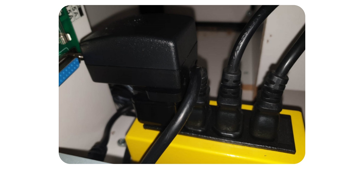
Plug the power supply for the raspberry Pi into the yellow box of the machine using the IEC adapter
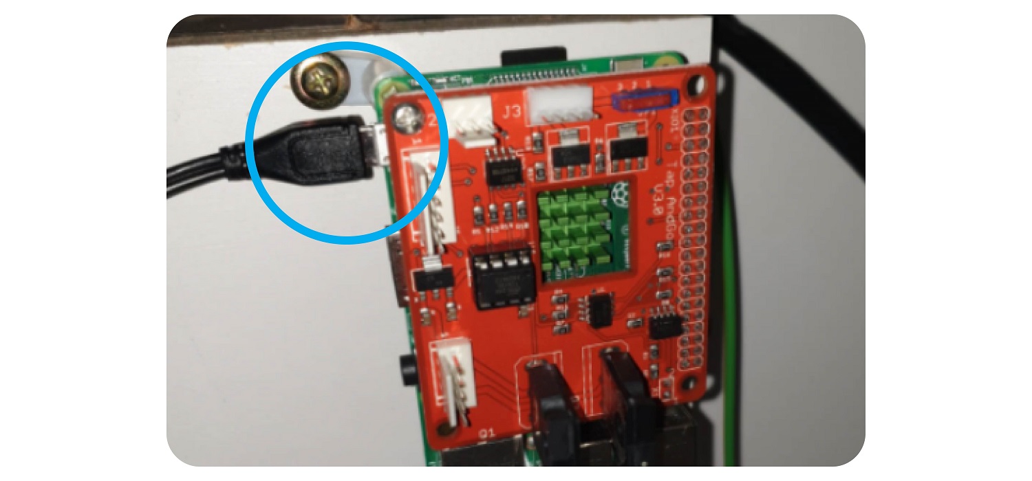
Plug the Micro USB cable into the Raspberry Pi
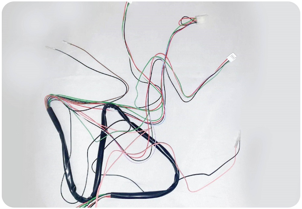
Step 4: Replacing the wiring to the Note Reader, Coin Mech, Tilt Sensor, Test button and connecting the Raspberry Pi.
Parts needed:Replacement wiring Harness
Step 5:
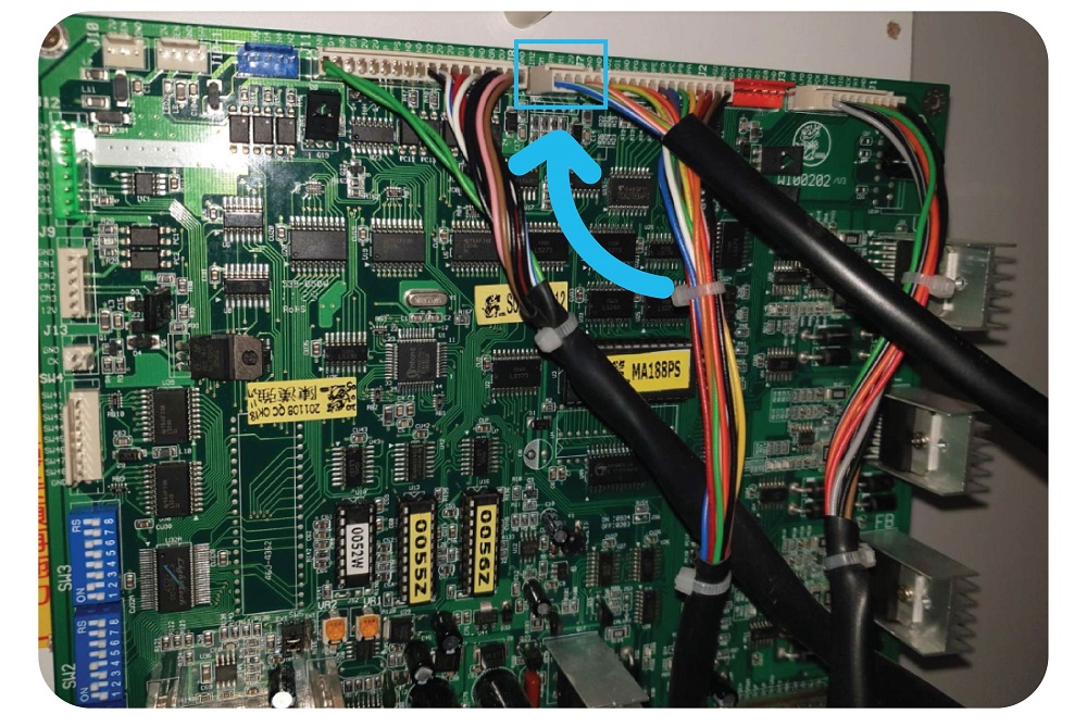
Remove the current wiring loom that runs from J8 on the motherboard:
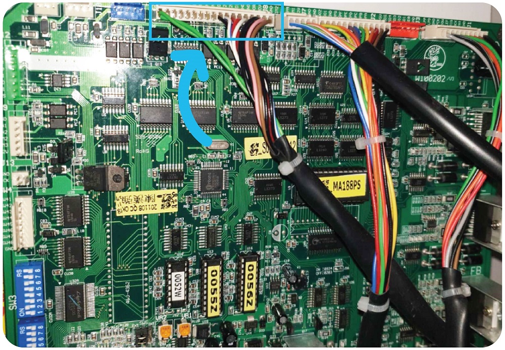
This loom runs to:
- Inhibit PCB next to Coin Mech
- Note Reader
- Test button
- Tilt Sensor
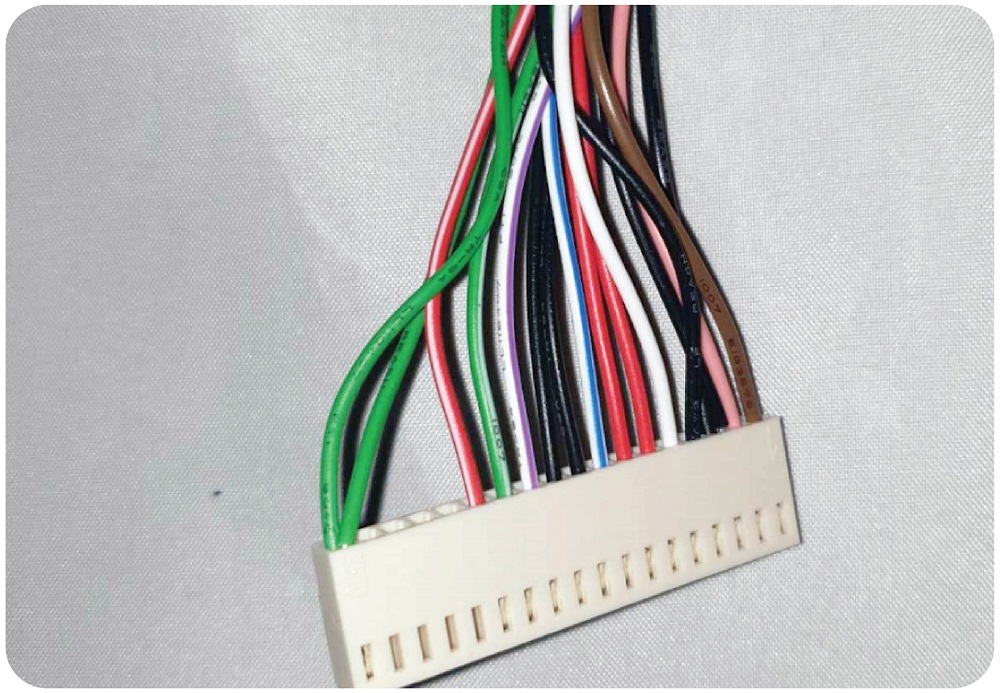
After removing the old wiring loom from all of the above components, plug the new wiring loom into the J8 connector on the motherboard.
Take the other connectors and connect those to:
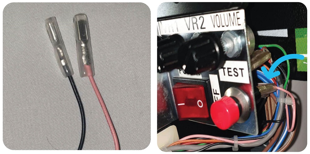
TILT SENSOR:
(It doesn’t matter which way around)
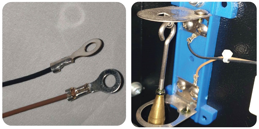
TEST BUTTON:
(It doesn’t matter which way around)
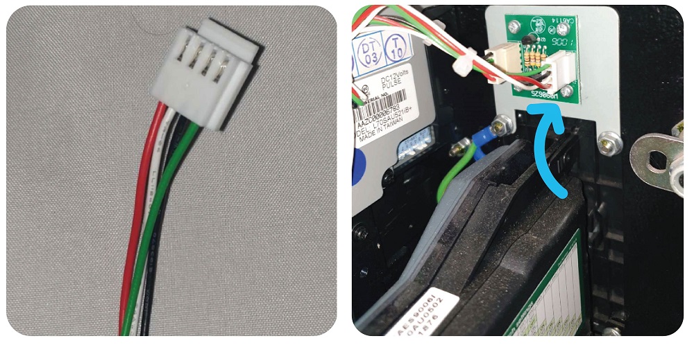
NOTE READER:
INHIBIT BOARD NEXT TO COIN MECH:
*IMPORTANT – please note the white wire is solid white
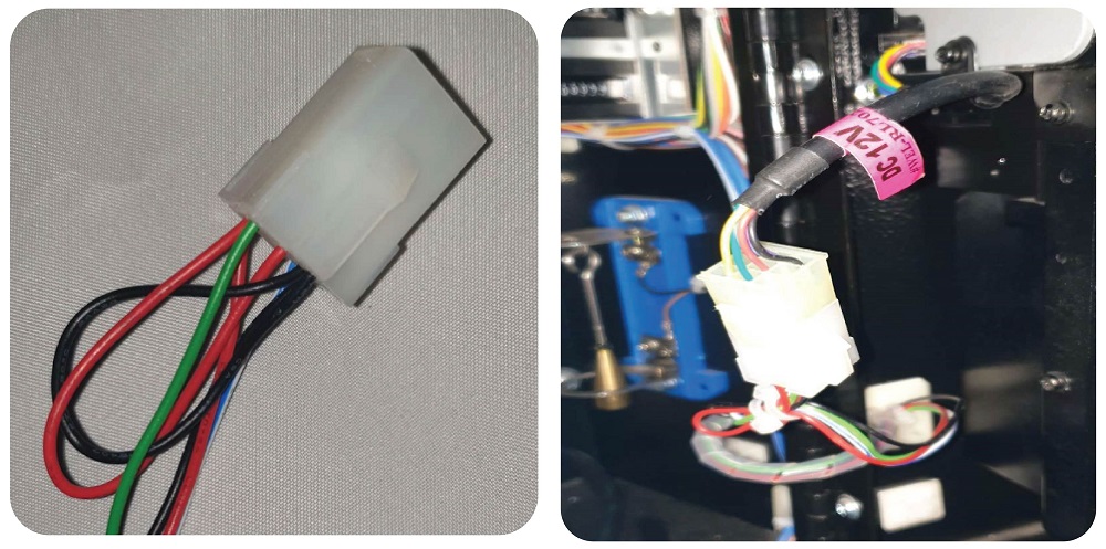
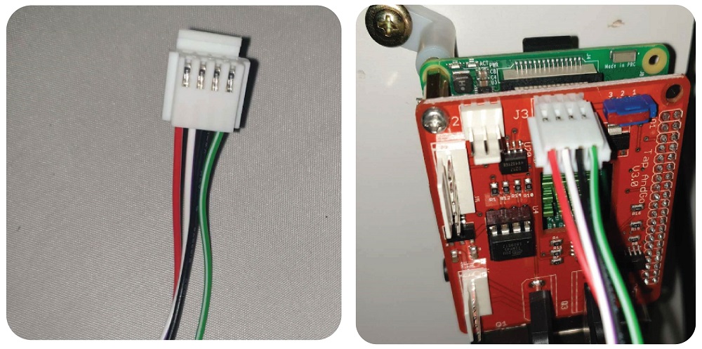
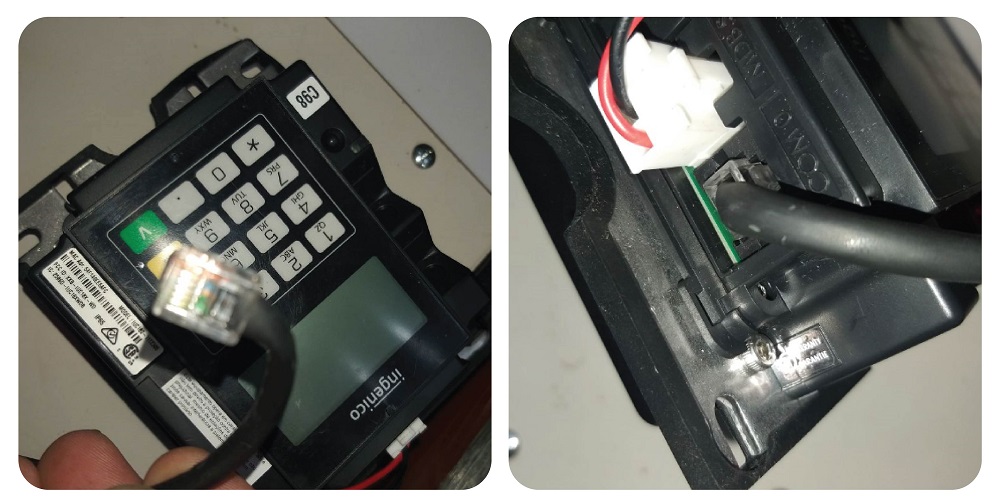
RASPBERRY PI:
*IMPORTANT – please note the white wire is PURPLE/WHITE
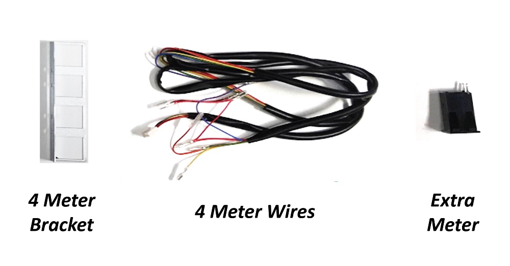
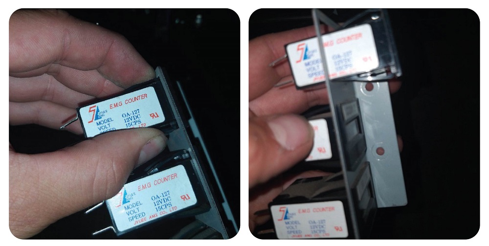
Step 6: Adding the 4th meter
For this step you will need 1 x 8mm socket set, 1 x meter wire, 1 x 4 meter bracket and 1 x meter.
Using the socket set, remove the nuts of the current bracket holding the meters on and remove the bracket:
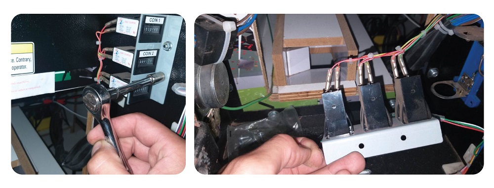
Then remove the wires from the back of the meter by pulling them:
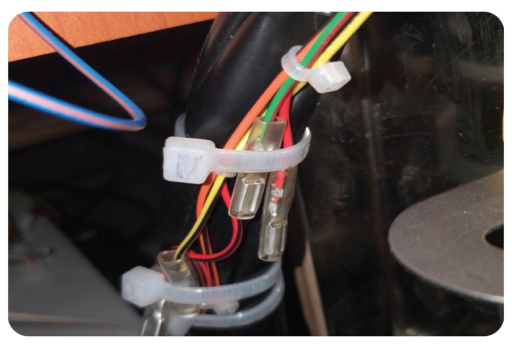
Once you’ve removed the wiring, tie it up like so to avoid confusion in future as this is now unused.
After removing and securing the wiring, you can pop the meters out of their current bracket by first squeezing the clips holding them in place, and them pushing them out from behind.
After you have removed all of the meters, put them into the 4 meter bracket like so, in the order of:
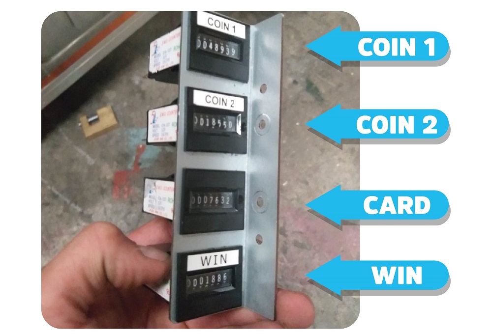
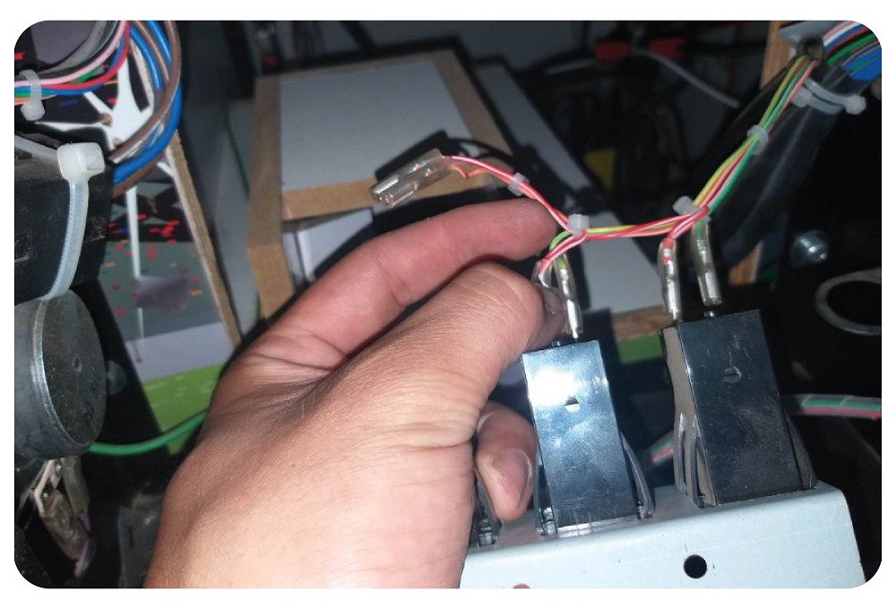
You can then connect the new meter wiring. Each meter will have 1 red wire connected to the top pin and another of a different colour connected to the bottom.
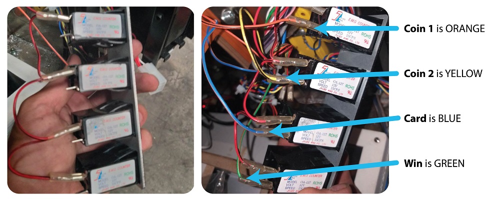
Once the meters are wired up like above, add the new 4 meter bracket in the place the old bracket was and secure with the nuts using your socket set.
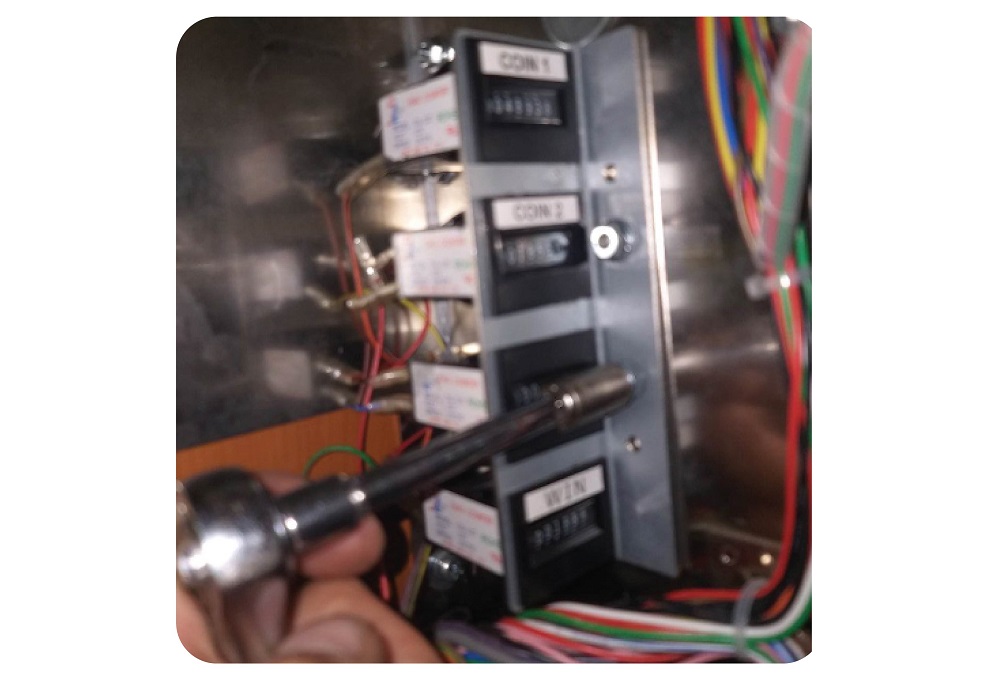
Run the wire to the back of the machine, and replace the connector at J7:
Step 7: Connecting the Pi and Router together
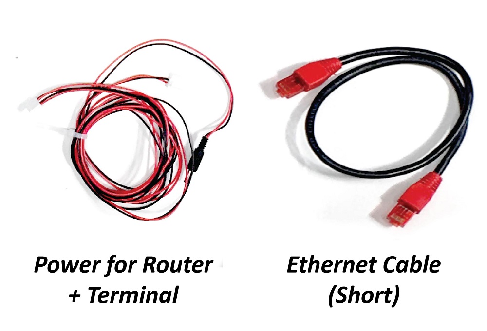
For this step you will need 1 x short Ethernet cable and 1 x Red and black power cable for router and terminal, and SIM card:
Take the SIM card and pop it out of the card:
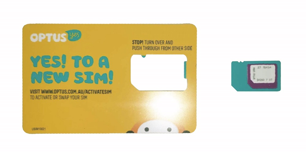
Pop the SIM out of the outer perforation to make it a ‘Micro SIM’ card:
Take the Router and turn it to the bottom. Take off the plastic guard covering the SIM Slot:
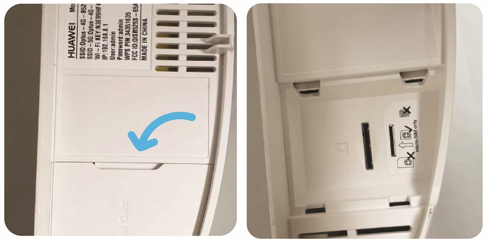
Insert the SIM card with the cut off corner facing down until it clicks into place:
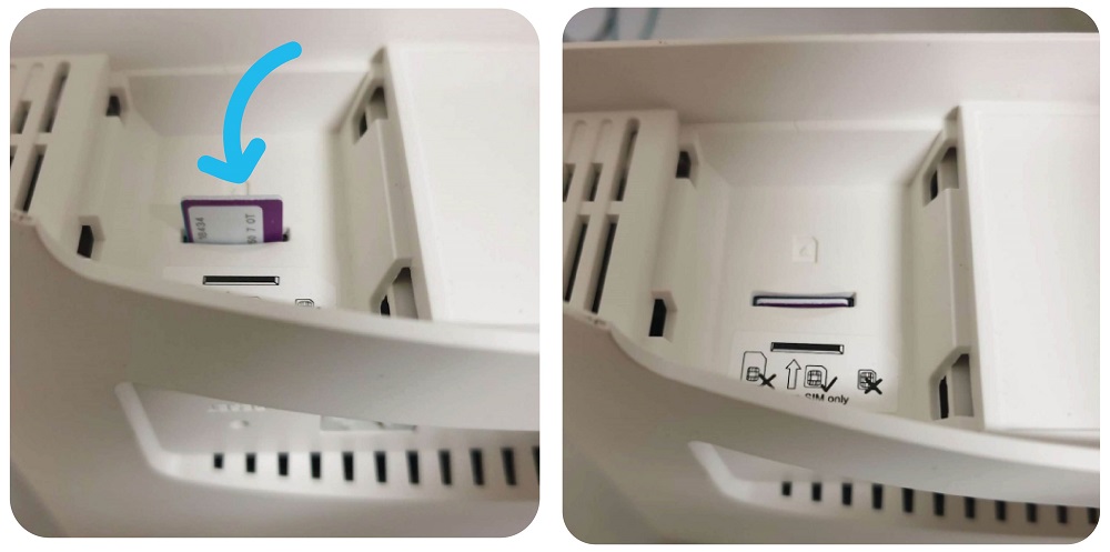
The re attach the plastic cover.
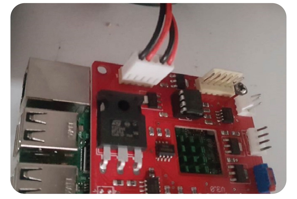
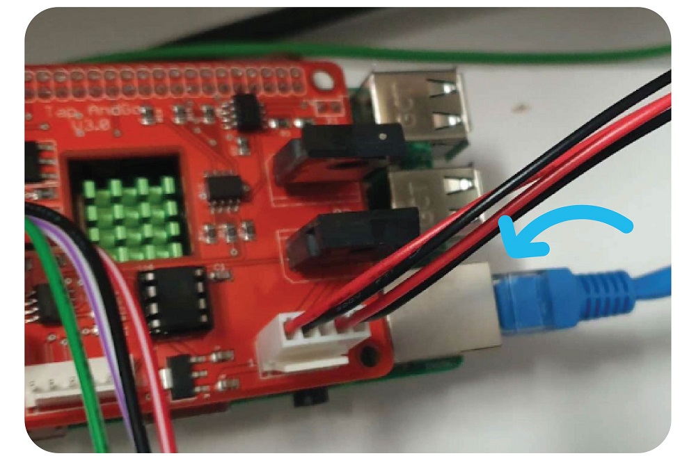
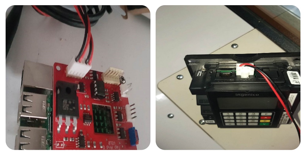
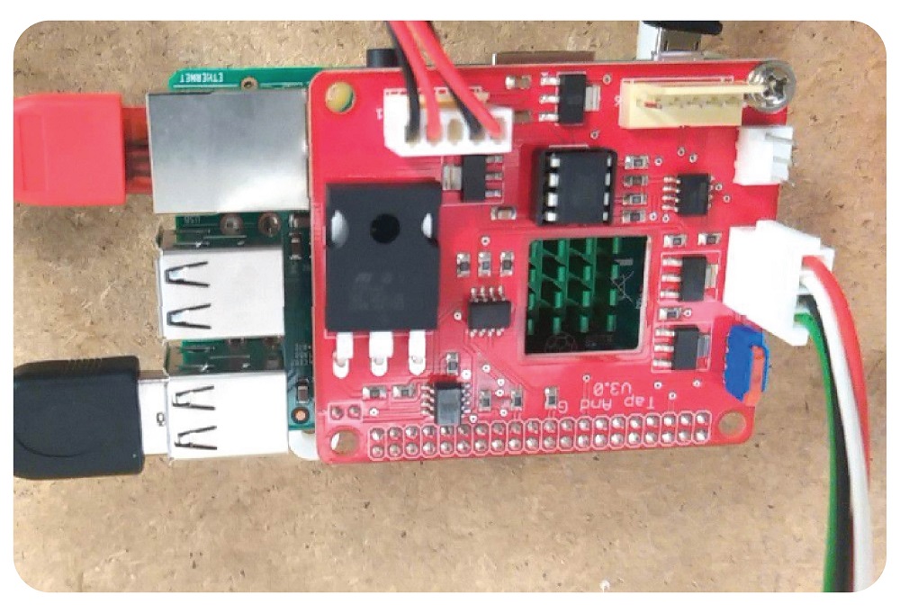
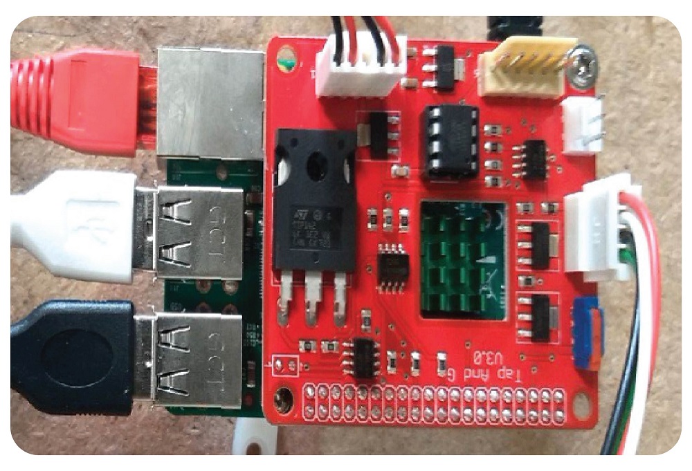
Take the black and red power cable and plug it into the red board of the Raspberry Pi, to the connector with 5 pins available like so, and the circular DC power connector into the Router like so:
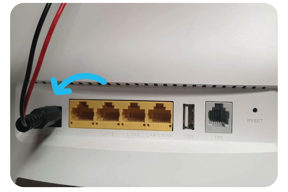
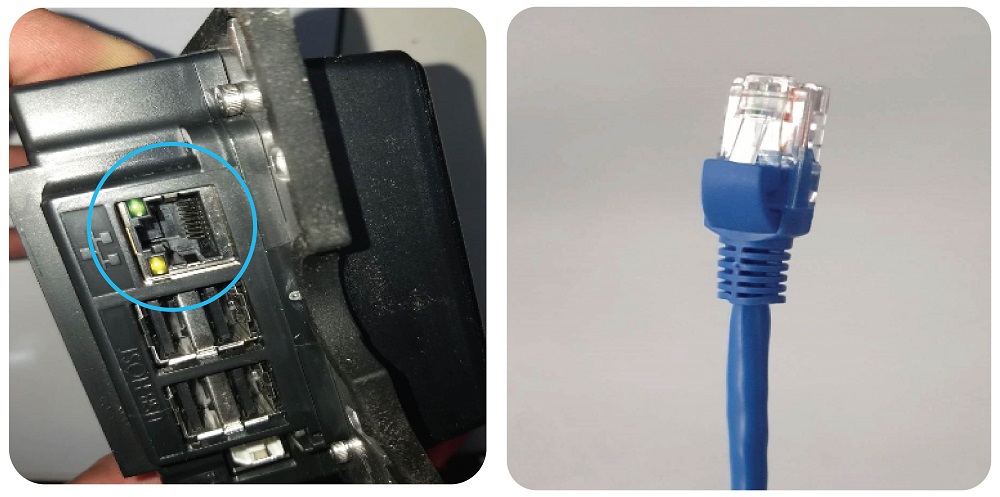
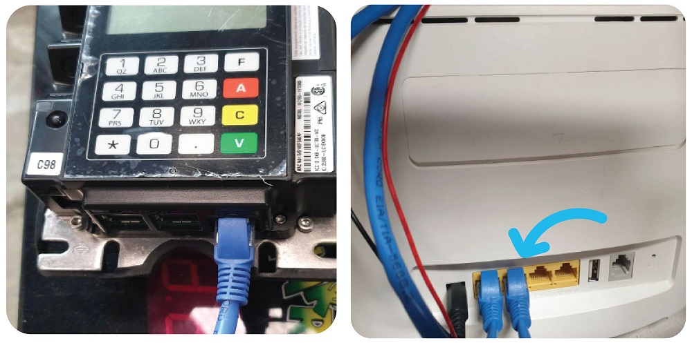
Then take the Ethernet cable, and plug it into the Ethernet port of the Raspberry Pi and into one of the yellow LAN ports of the router like so:
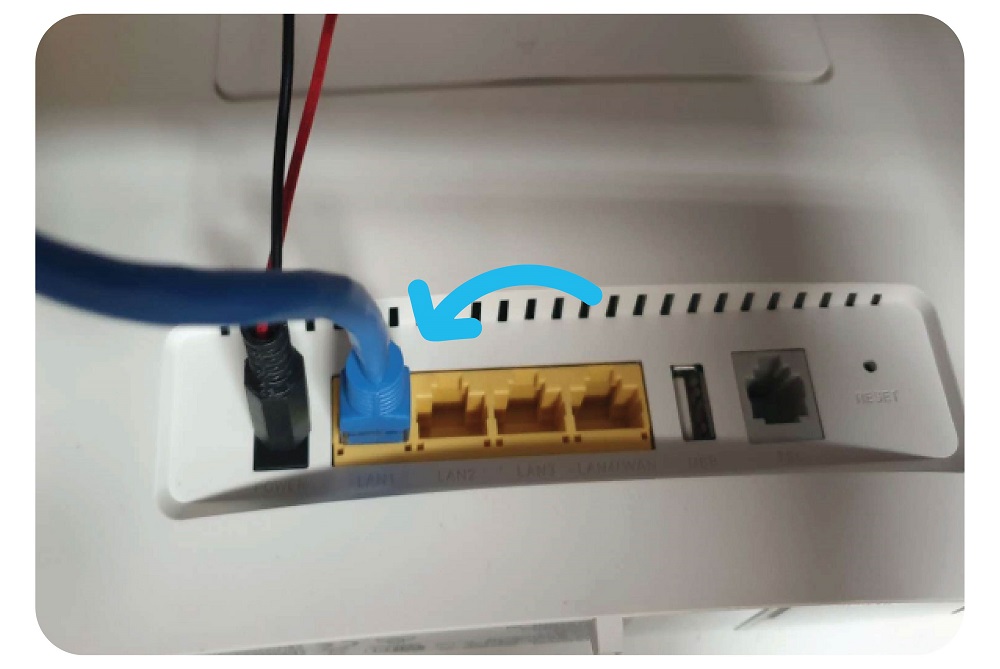
Hint: Ensure it goes into the yellow LAN port of the router- it will not work as intended if you plug it into the grey WLAN port.
Step 8: Making a hole for the wires
Tools needed: Drill with large drill bit
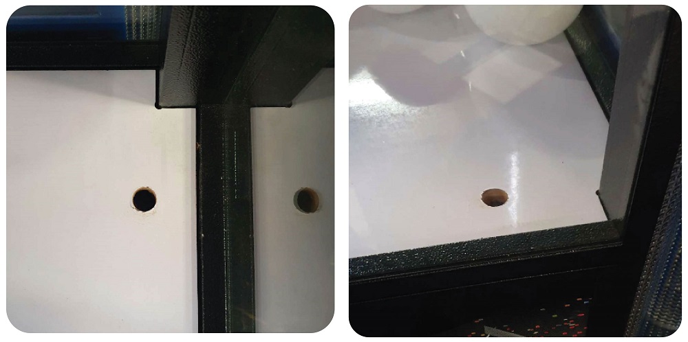
Using a marker pen, mark on the playfield exactly where the wires will need to pass into the bottom of the machine.
Take the drill and make a hole in the playfield, near the front window to the right hand side. This should be around 20 mm diameter:
Step 9: Connecting the Pi and the Terminal
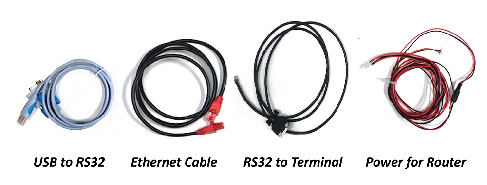
For this step you will need 1 x long Ethernet cable, 1 x Red and black power cable for router and terminal 1 x USB to RS32 Serial convertor and 1 x RS32 Serial Cable to terminal:
Take the red and black cable you have already plugged into the Raspberry Pi & Router plug the remaining connector into the Terminal like so:
Take the Ethernet cable, and plug it into the Ethernet port of the Terminal at the bottom left, and plug the other end into one of the yellow LAN port of the router like so:
Take The USB to RS32 Serial Cable and the RS32 Serial to Terminal Cable, connect together and use in built screws to secure like so:
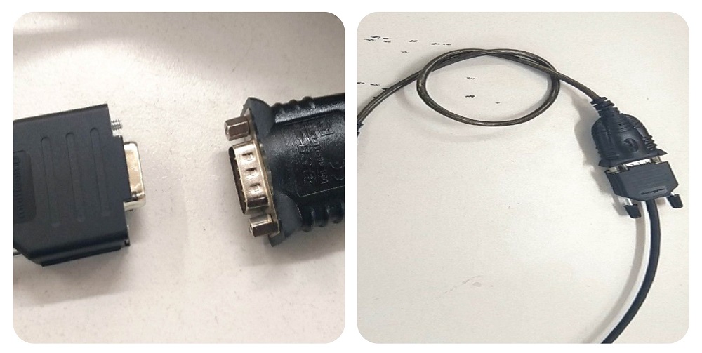
Then take the USB end of the USB to RS32 Serial cable and plug into the USB port of the Raspberry Pi:
Take the other end of the RS32 Serial to Terminal cable and place it in COM 0 port of the terminal like this:
Step 10:
Placing the terminal into the case:
Take the front part of the case (with white LED strips already installed) and gently push the face of the terminal in until it clicks into place, like so:
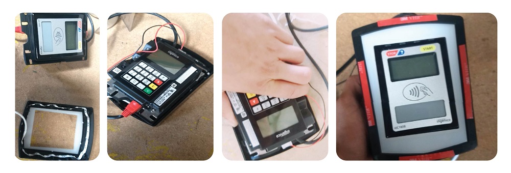
Then take the rear of the case, an line each of the wires from the terminal into the 3 holes available like so:
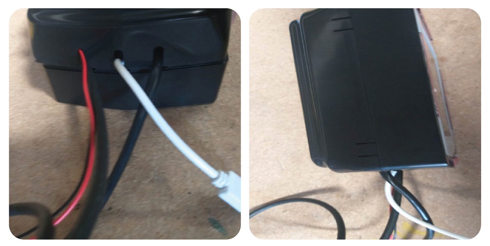
Then close the case until it clicks into place, end result:
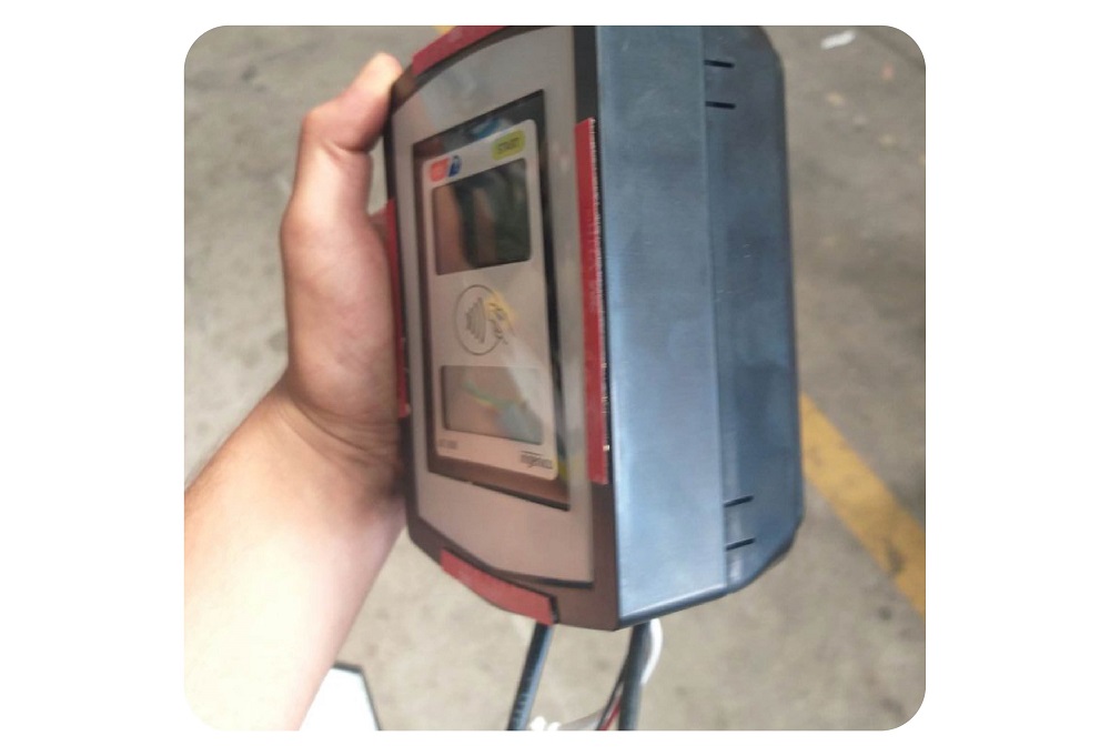
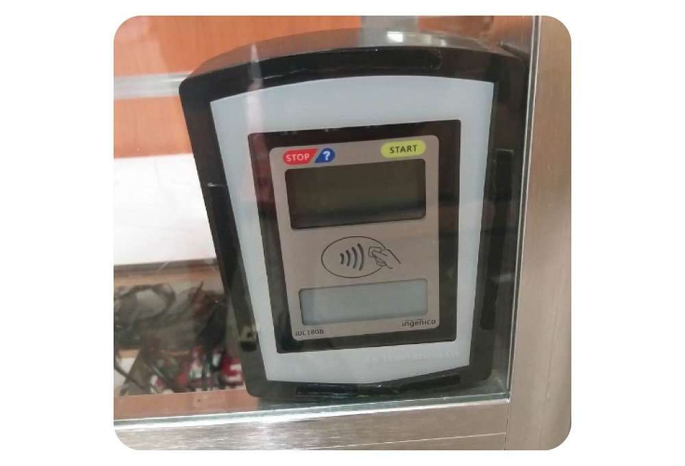
Step 11: Mounting the case and terminal to the window
Peel the protective layer of the double sided glass tape already stuck to the case.
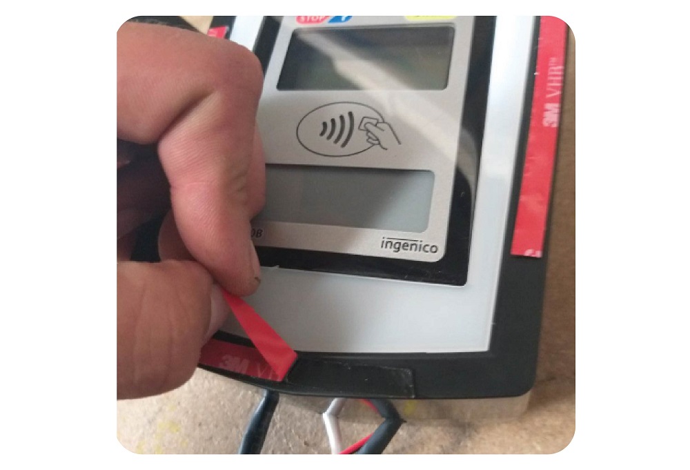
Line up the case with the desired part of the window ,making sure the case is stuck on absolutely straight. Then, using reasonable force press the taped part of the case to the window and hold for 5 seconds.
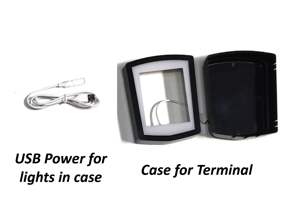
Step 12: Connecting the LED strip of the case to the Raspberry Pi.
Parts needed: Case with LED strip installed, White 4 Pin to USB connector with button control:
Connect the 4 male pins together with the female connector – making sure the arrow is pointing to the + symbol.
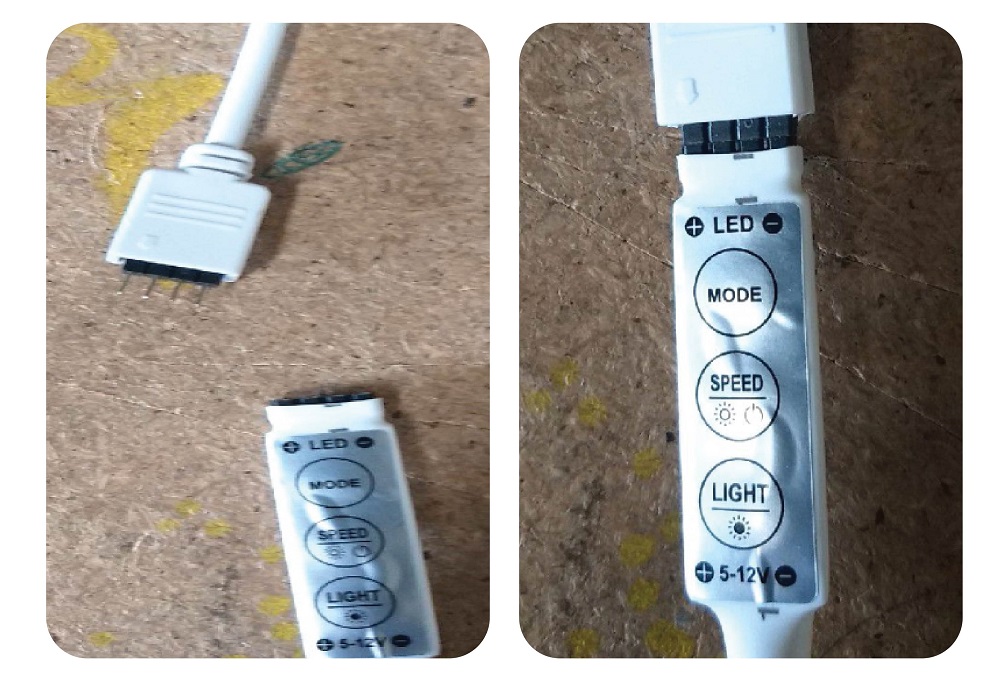
Then, using electrical tape, tightly secure the two together like so:
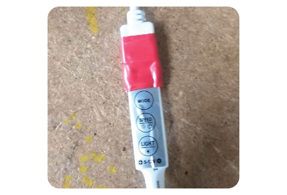
Then, take the other end of the white wire – USB cable – and insert into the USB port of the Raspberry Pi like so:
Step 13: Tidying all wires together
Using cable ties , cable tie together the 4 wires leading up to the terminal at multiple points down the wire, to keep them neat and together.
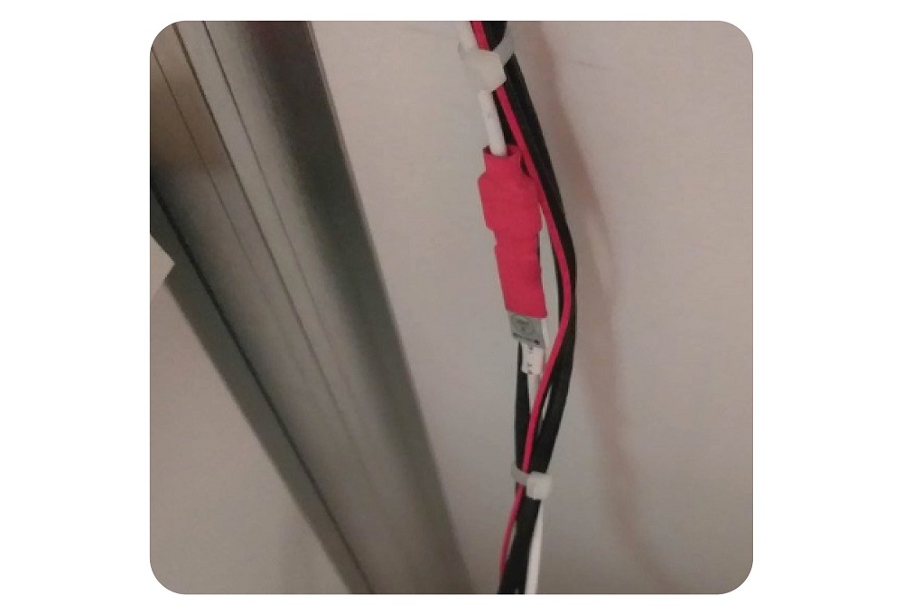
Secure and neaten any other loose wires using cable ties, and using self adhesive cable tie.
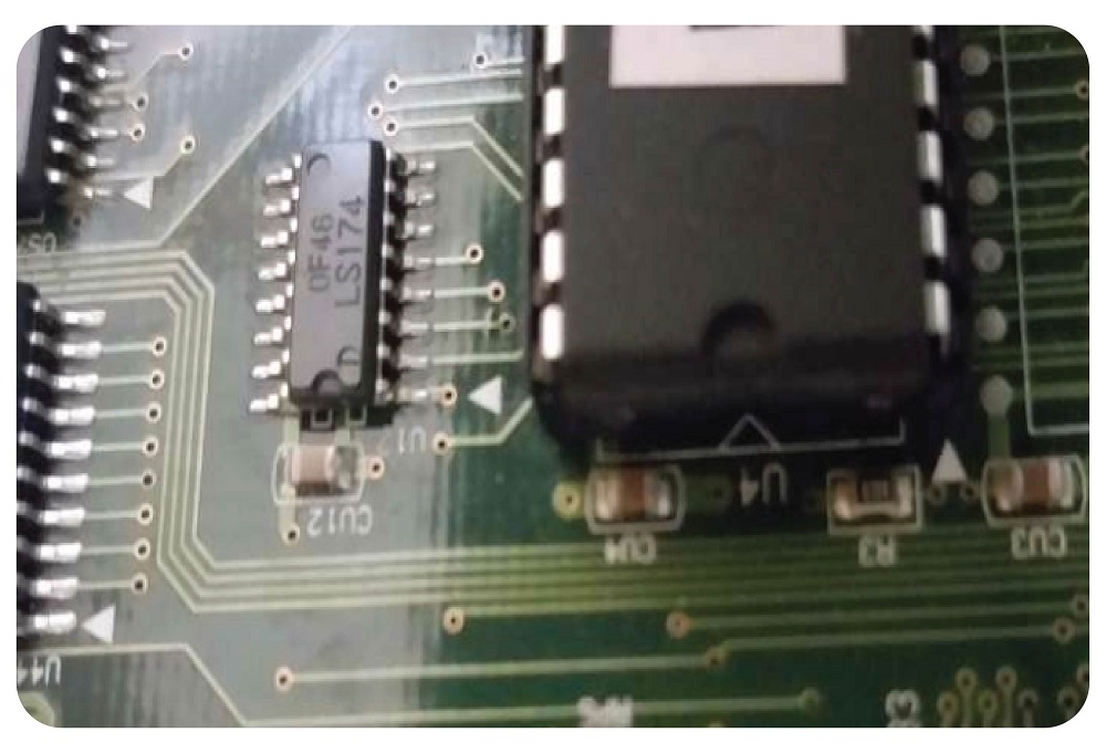
Step 14: Change the Program Chip
The relevant program chip is included in your readymade kit.
Remove the one in there with a tool or screwdrivers.
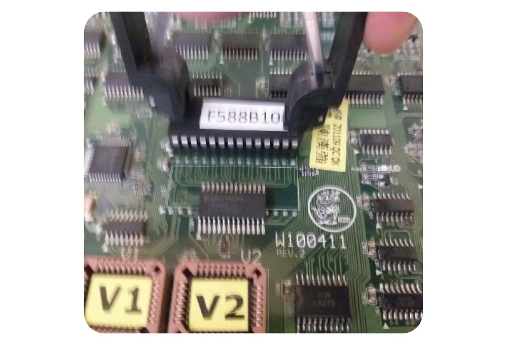
Then, carefully insert the replacement with the indent shown on the chip pointing this way:
Ensure all of the legs line up perfectly with the holes before pushing down.
Step 15: Settings
NON LCM Machines (STD)
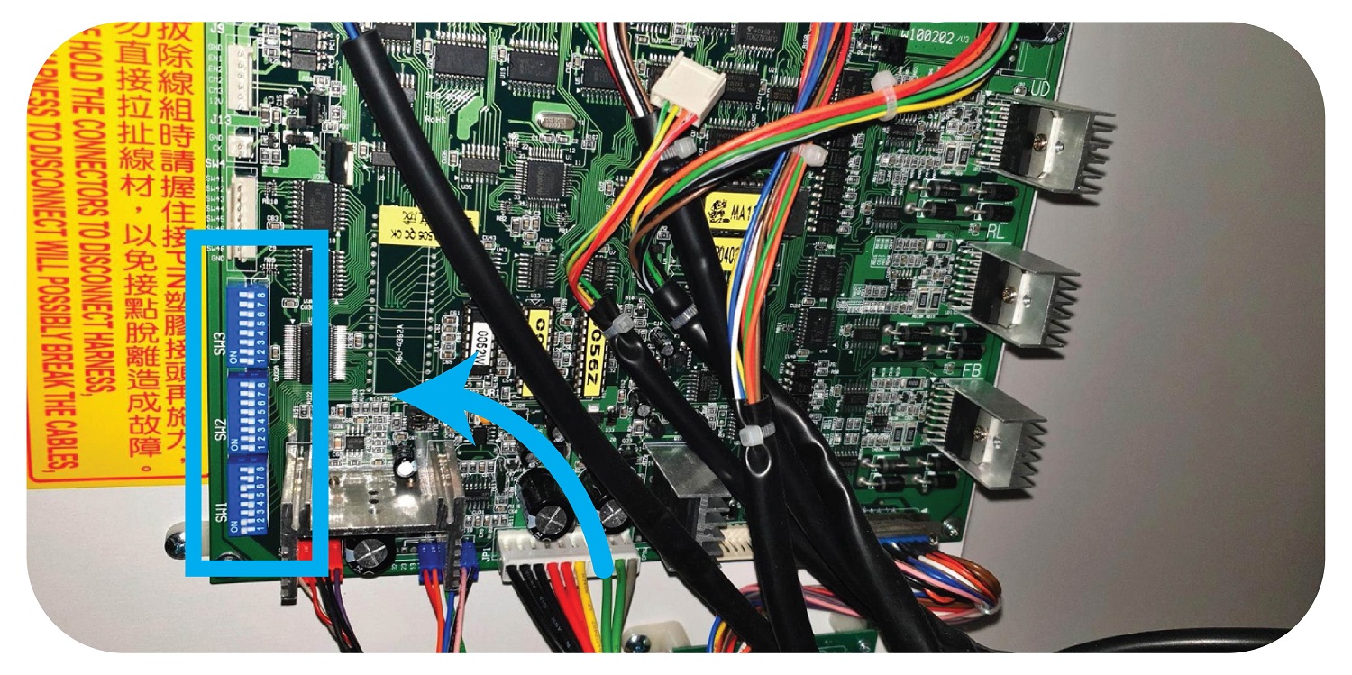
Turn off the machine
Turn on dip switch 7 of bank 2 on the main PCB, then power up the machine.
Go to the front of the machine and change the following options to the following values using the joystick and drop button and credit display.
| Option | Value | ||
| 03 | 02 | ||
| 04 | 01 | ||
| 05 | 05 | ||
| 06 | 03 | ||
| 09 | prize setting as desired | ||
| 12 | 05 | ||
| 13 | 03 | ||
| 16 | 05 | ||
| 17 | 03 |
Turn off machine
Turn off dip switch 7, Bank 2.
Power on machine
NON LCM Machines (THE CLAW)
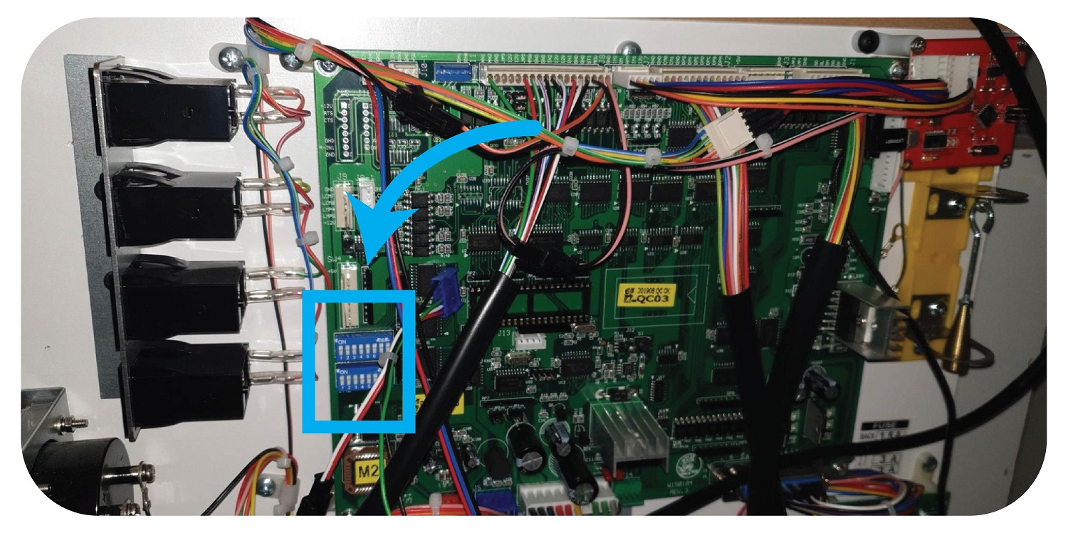
Turn off the machine
Turn the machine back on whilst holding the test button until the credit display flashes PP.
Go to the front of the machine and change the following options to the following values using the joystick and drop button and credit display.
| Option | Value | ||
| 09 | prize setting | ||
| 12 | 05 | ||
| 13 | 03 |
Turn off machine
Go to the PCB and find the dipswitches. Go to SW2 and turn on 2,3 4. (SW2 should now have 2,3,4,6 ON)
Restart the machine.
Test.
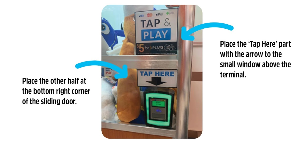
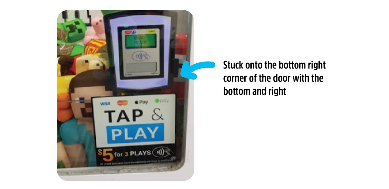
Step 16: Installing the Sticker
Standard / Large

Jumbo / Maxi Claw
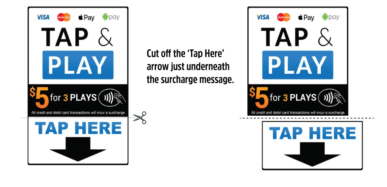
The Claw Large
Step 17: Let us know the install is complete
Send an email to Techsupport@coinopgroup.com with the machines serial number and a picture of the new meters, We will then ensure this is added to the software.