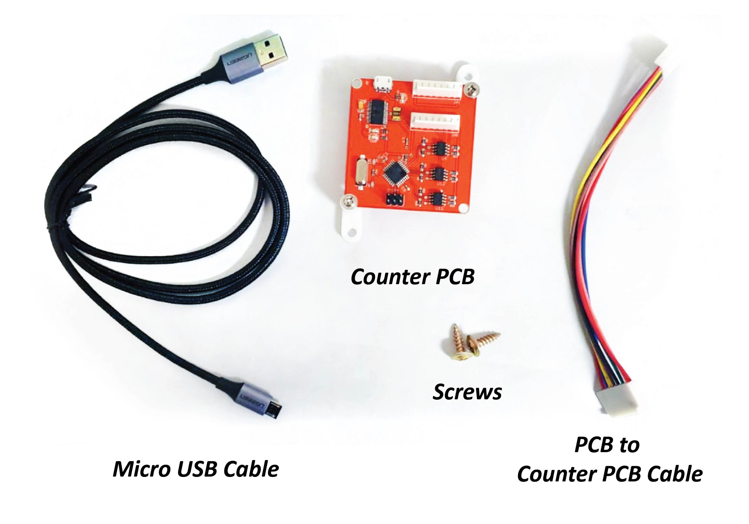
Parts Needed
- 1 x Counter PCB
- 1 x Micro USB cable
- 1 x Pcb to Counter PCB Cable
- 2 x Screws
Step 1:
For Large, Jumbo:
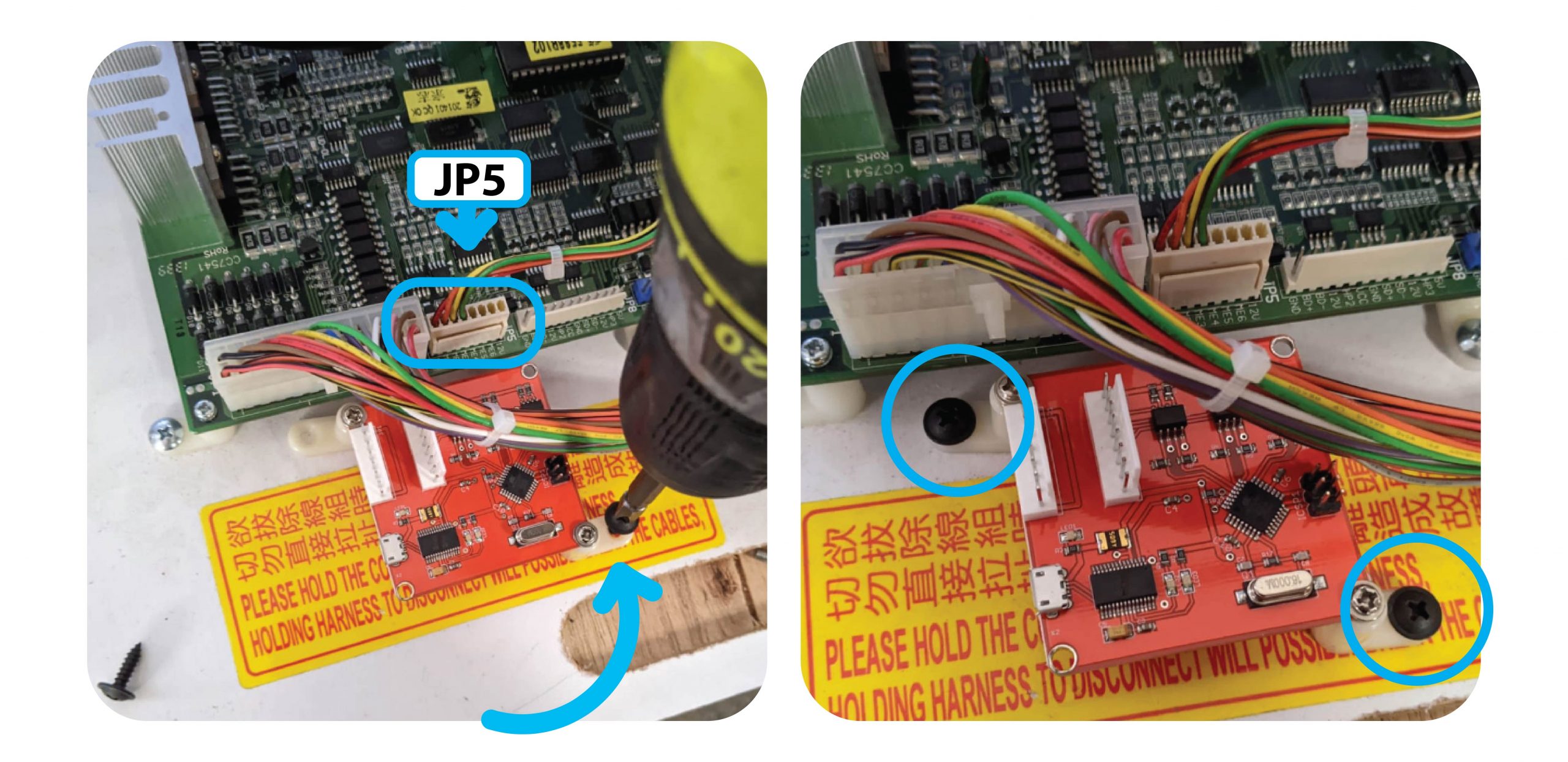
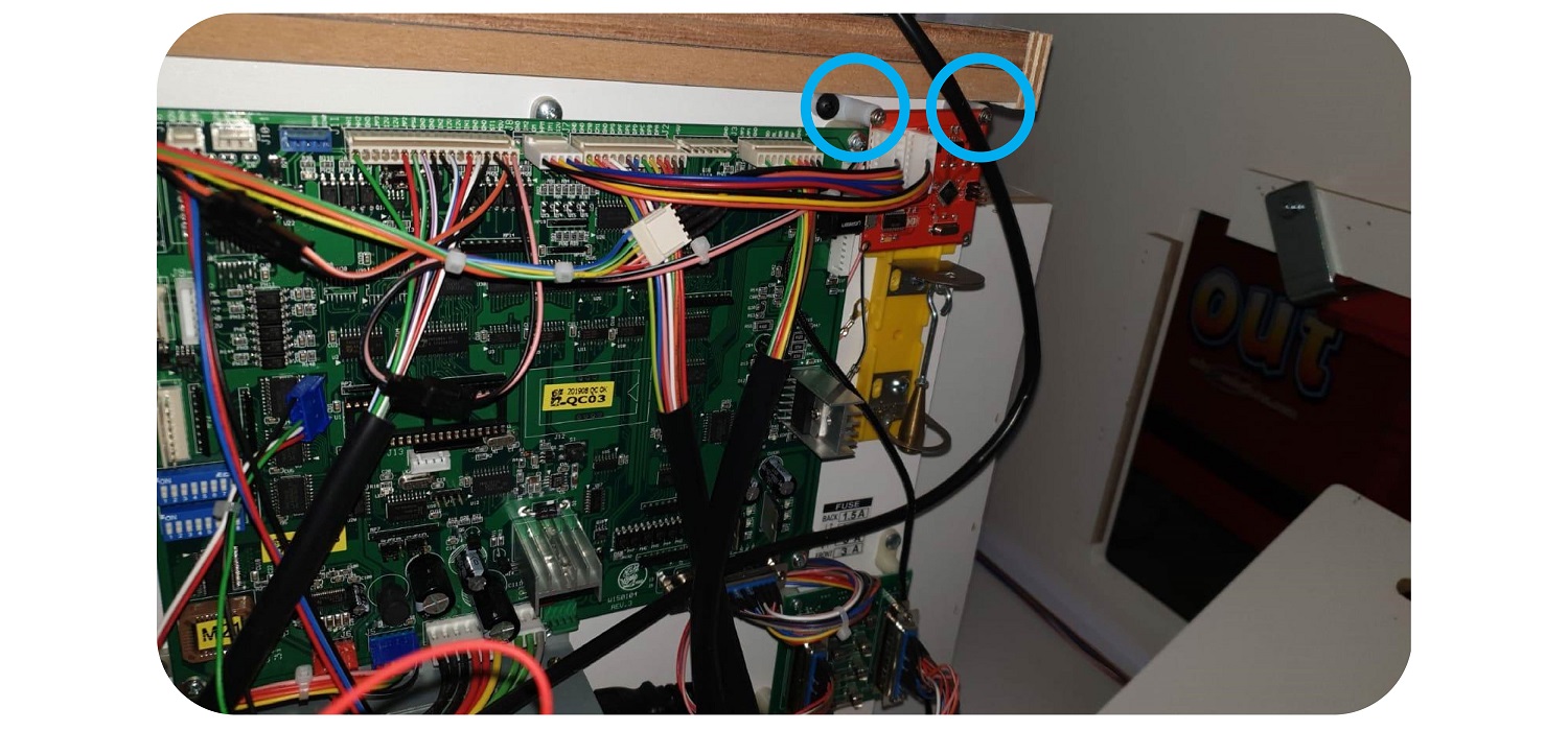
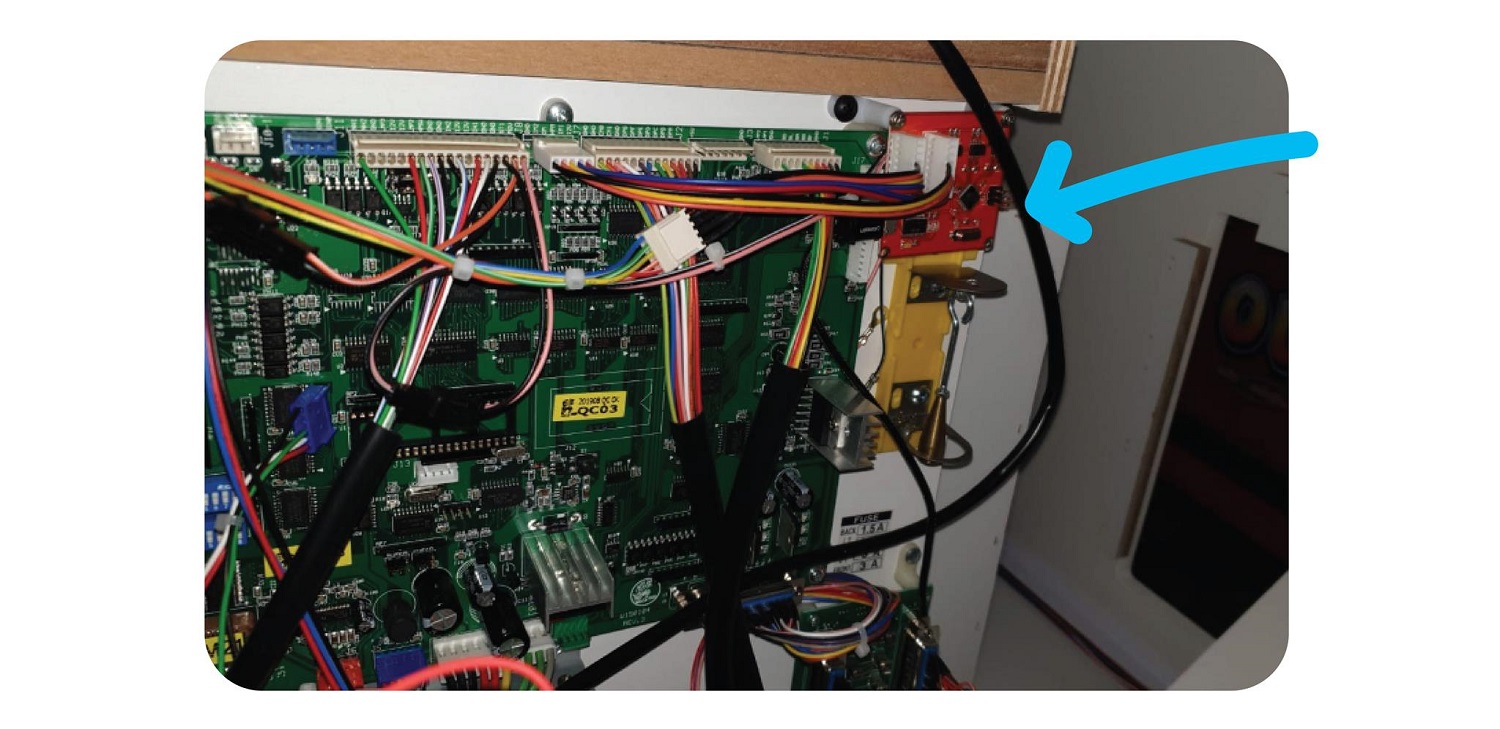
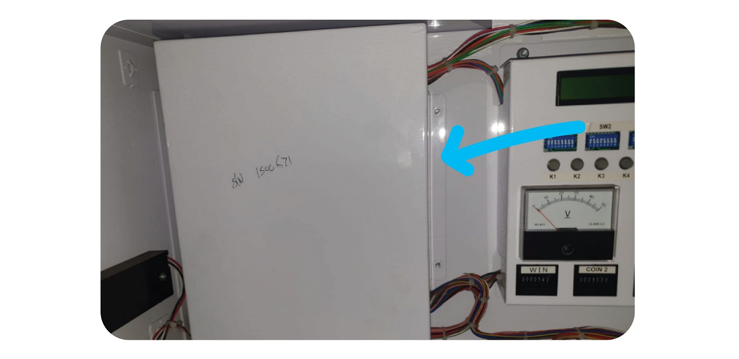
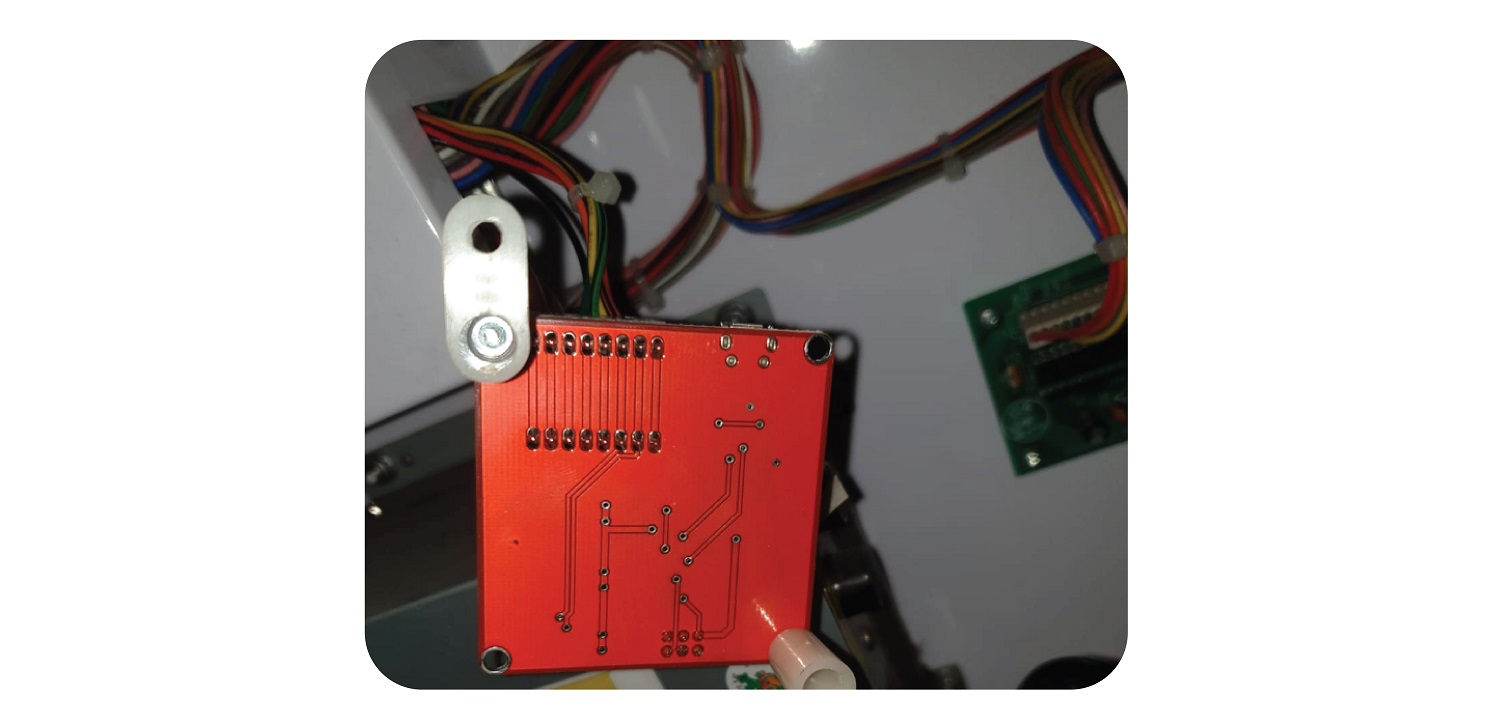
Open up the back of the machine and screw the new board onto the sliding board that houses the PCB, next to the JP5 port.:
For The Claw Large, install the 2 feet at the top of the Counter PCB.
Install it to the right, above the Tilt Sensor like so
Step 2:
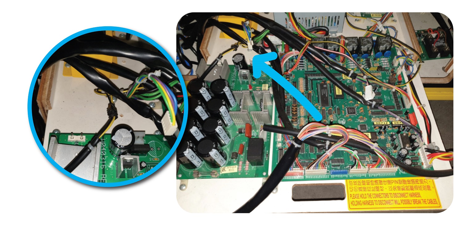
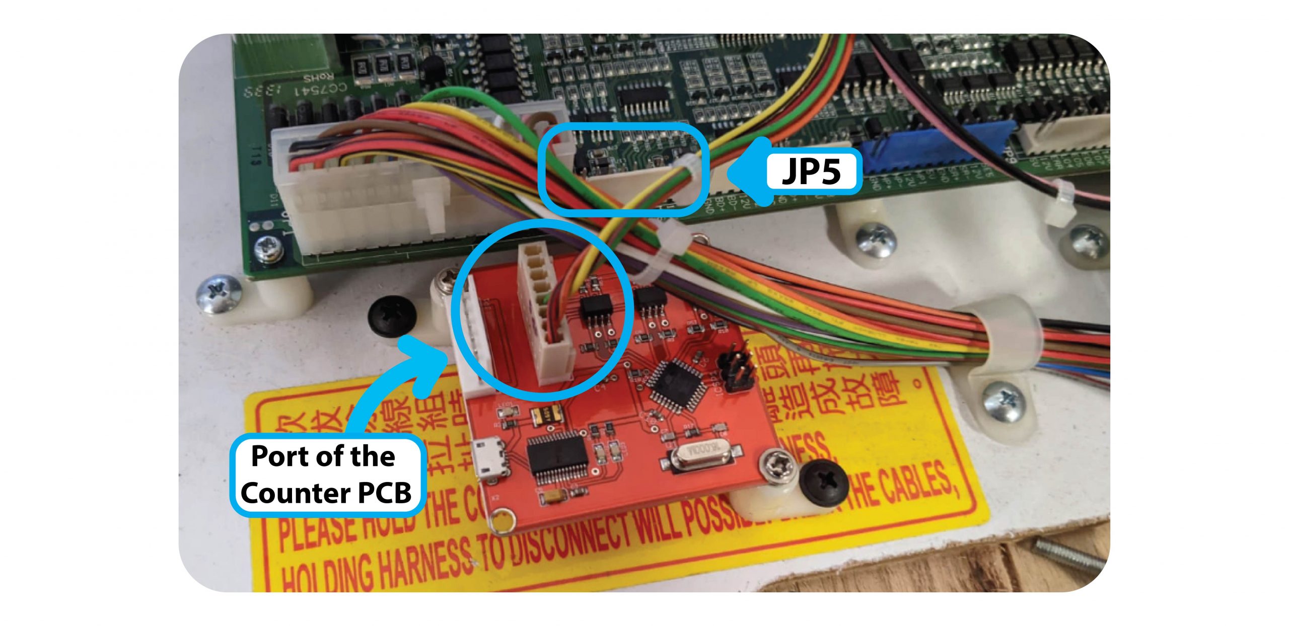
Remove the Meter wire from the JP5 connector, and add it to the inside port of the Coin & Bill counter:
Step 3:
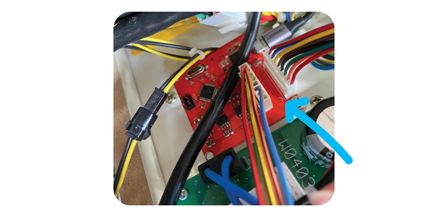
Add the PCB to Counter PCB Cable to the outside port of the counter PCB.
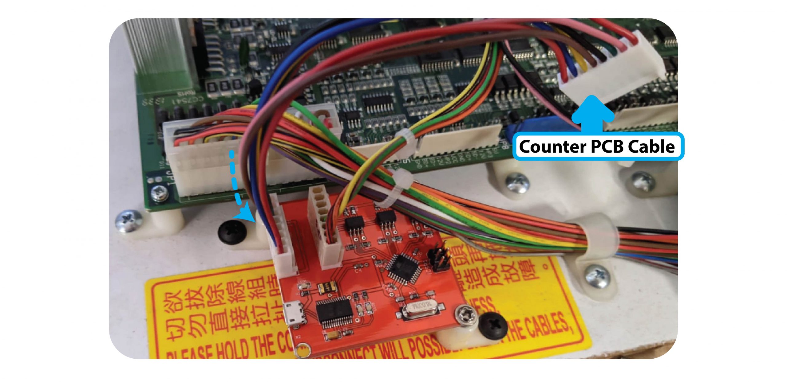
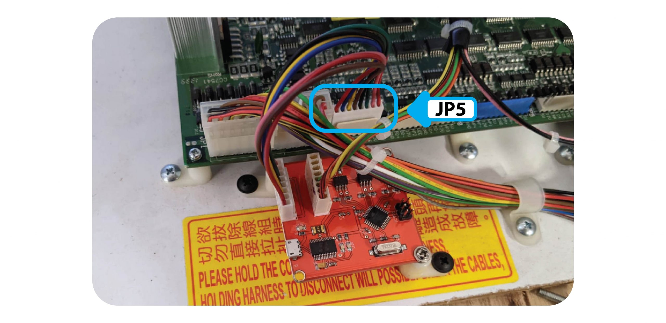
Then connect this Cable to the JP5 Cable of the board:
Step 4:
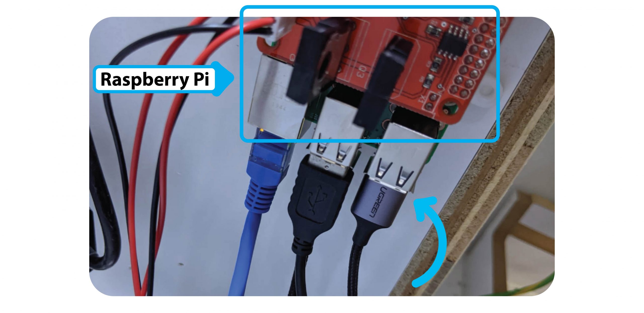
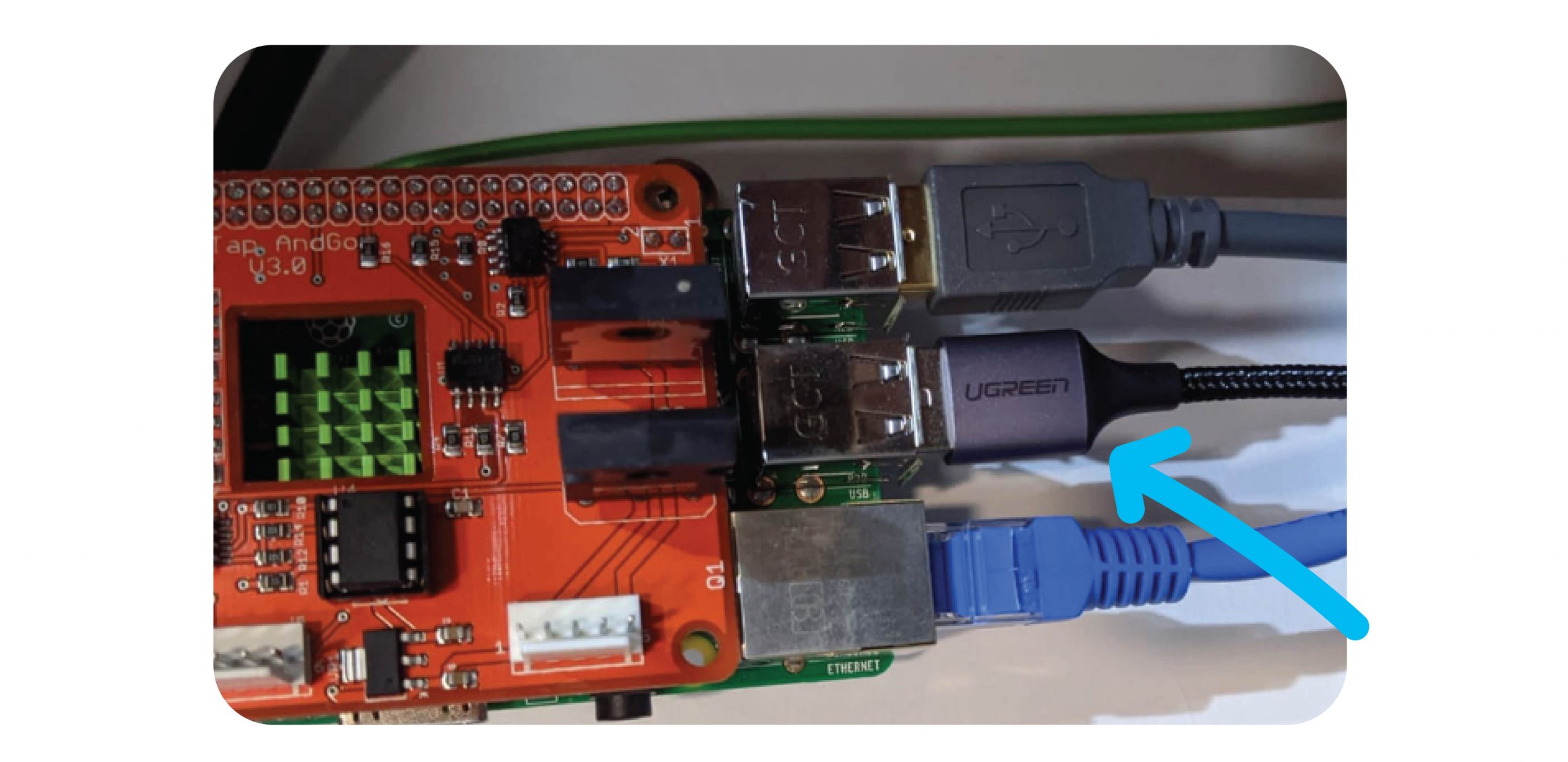
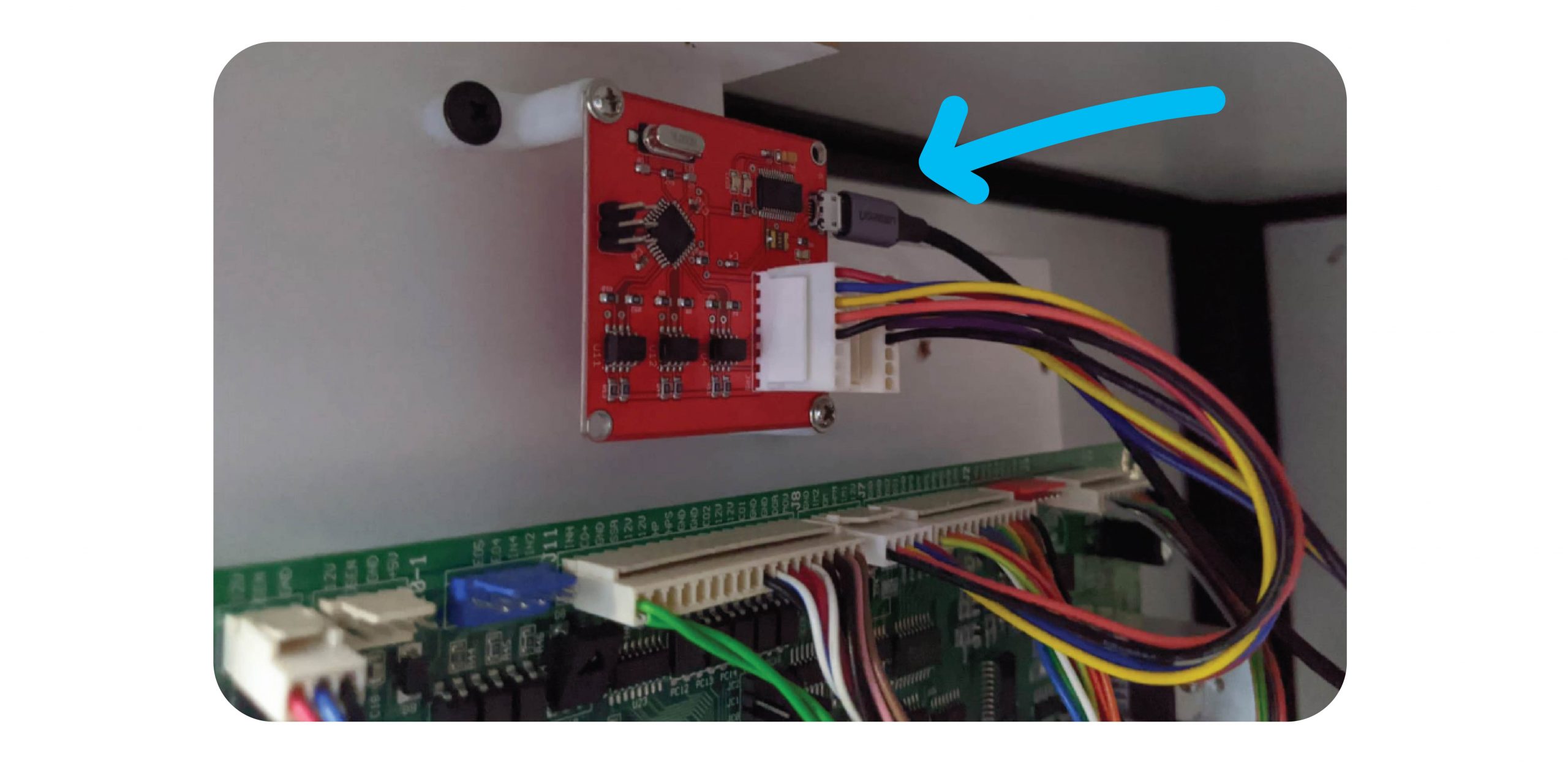
Connect the Micro USB cable between the Raspberry Pi and the Coin & Bill counter.
Step 5: Test
Test coins, notes & 1 x win with money. Make sure all meters tick properly.
Contact Joven or JohnLehmar via Whatsapp and confirm the logs are coming through.
For The Claw Large & Standard Machines
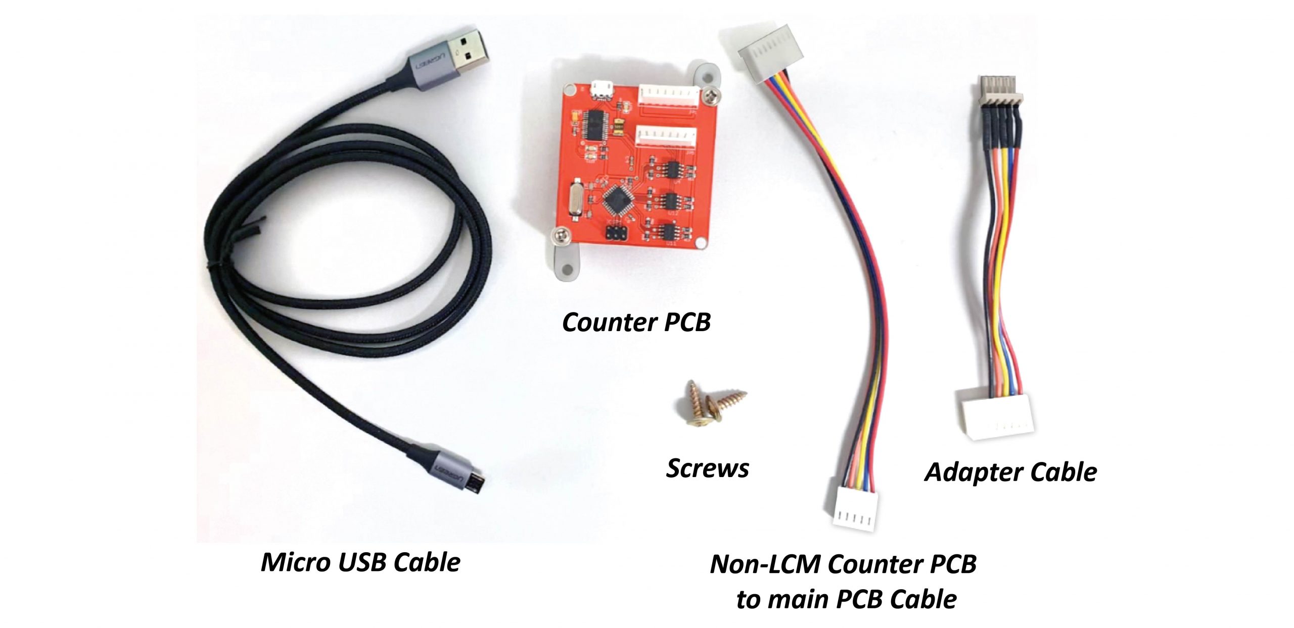
Parts Needed:
- 1 x Counter PCB
- 1 x Micro USB Cable
- 1 x Non-LCM Counter PCB to main PCB cable
- 1 x Adapter cable
- 2 x Screws
Step 1:
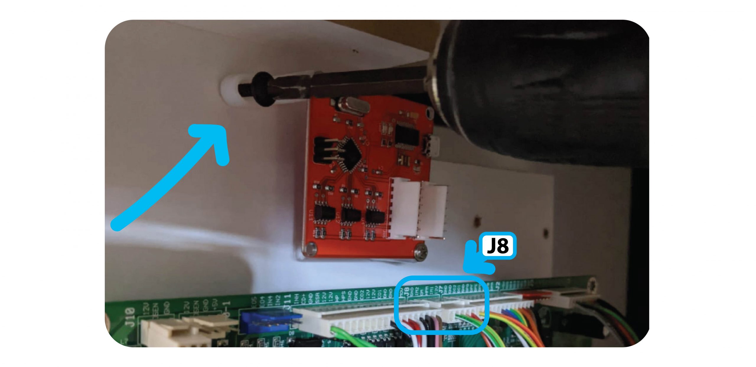
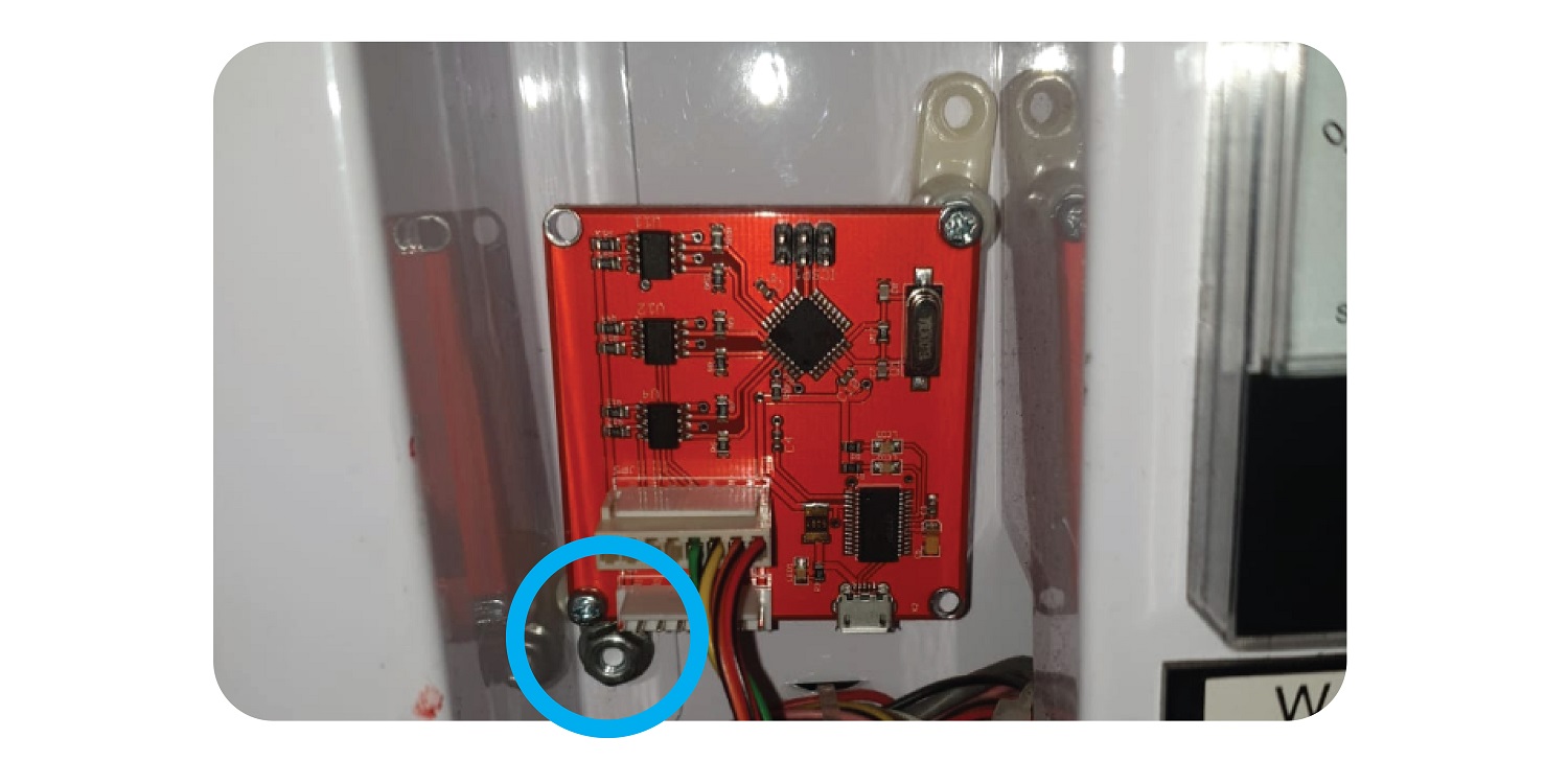
Open up the back / front of the machine and screw the new board onto the sliding board that houses the PCB, above the J8 Port:
For The Claw Large install the counter to the right above the Tilt Sensor:
Step 2:
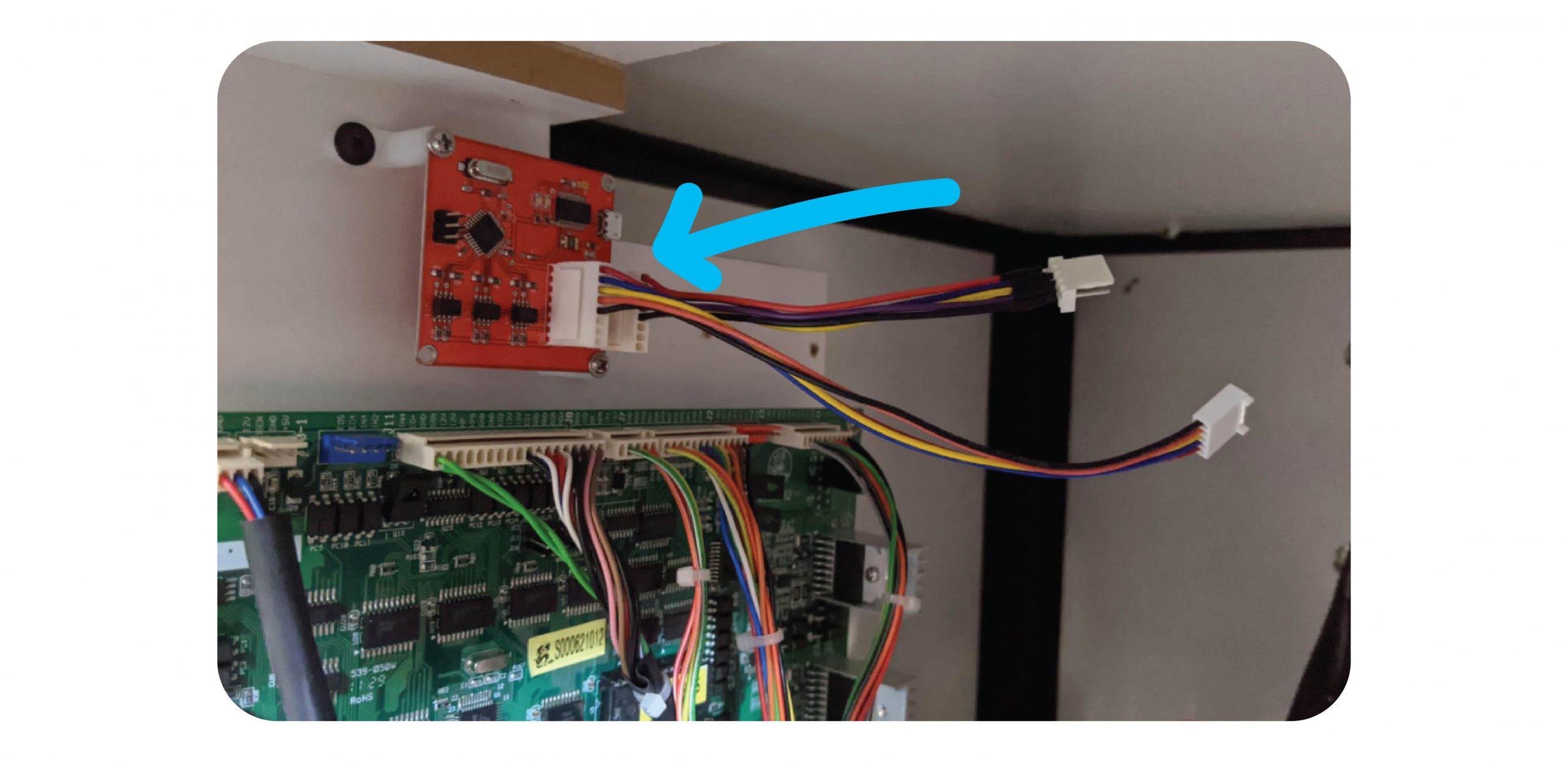
Add the Non-LCM Counter PCB Cable to the Inside port of the Counter PCB, and the adapter wire to the outside port:
Step 3:
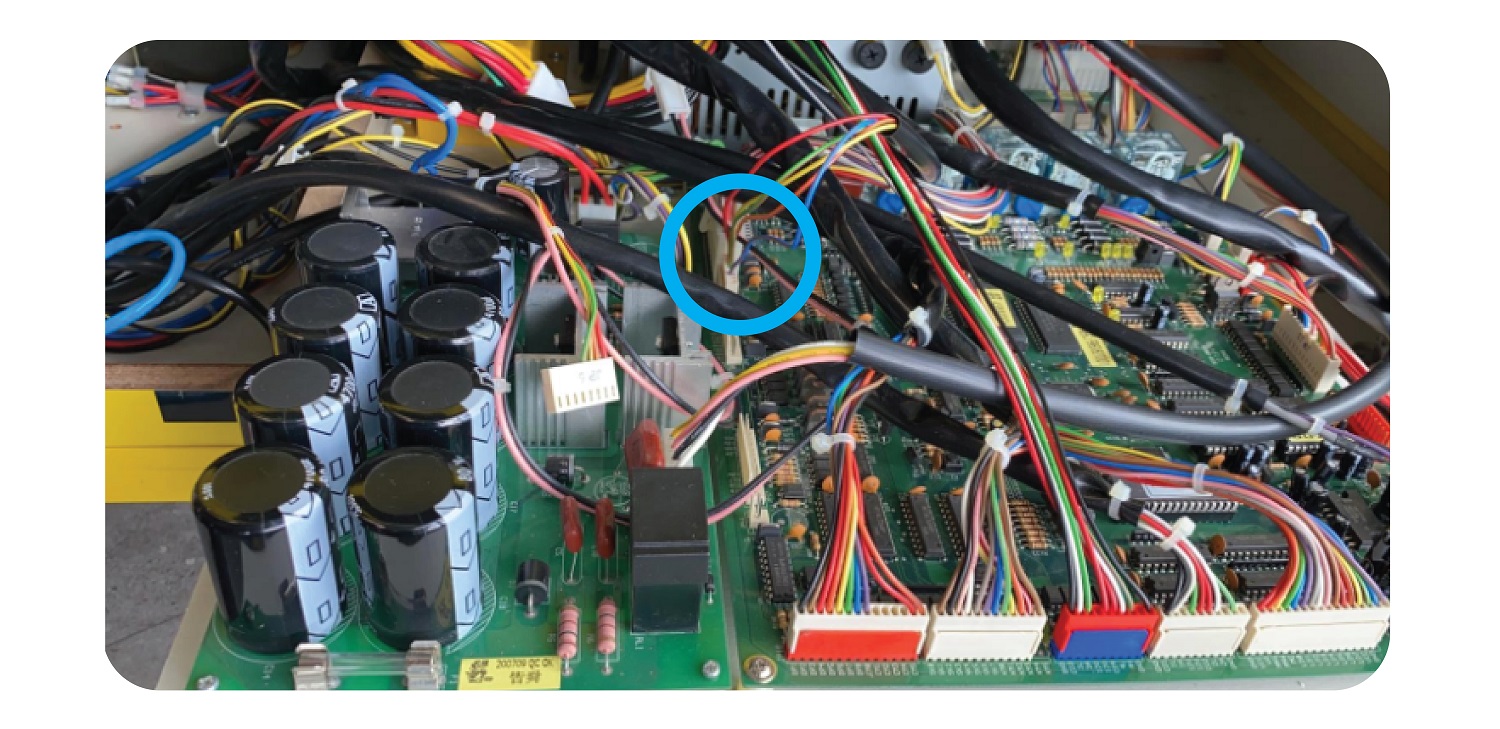
Remove the J8 connector and plug this into the adapter wire:
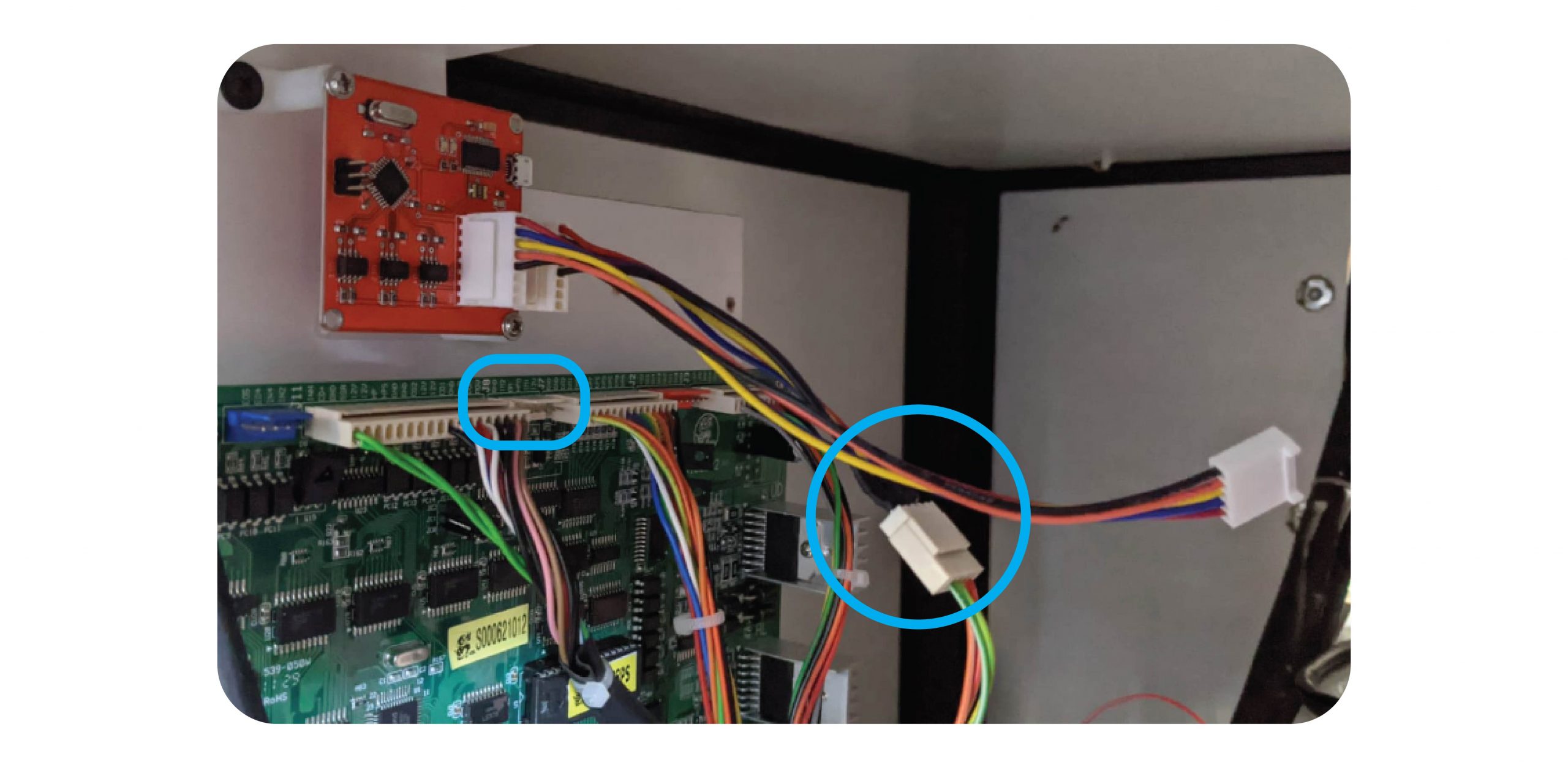
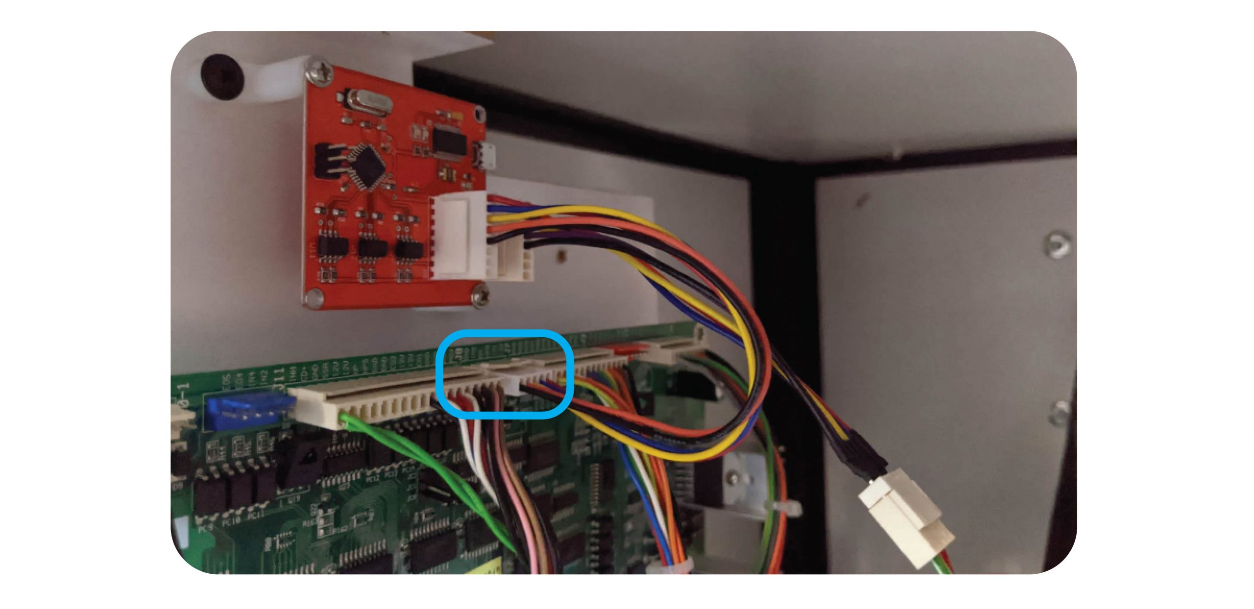
Then connect the PCB to Counter PCB cable to the J8 connector:
Step 4:
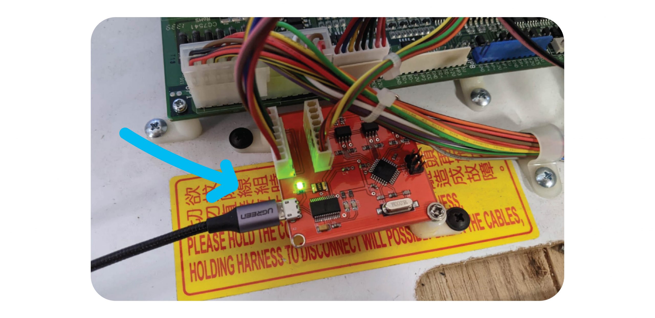
Connect the Micro USB cable to the Counter PCB and the Raspberry Pi:
Step 5: Test
Test with coins, notes & 1 x win with money in this order:
- Coins
- Notes
- Win
Make sure all meters tick properly.
ENSURE ALL TEST GOES ARE ENTERED INTO THE SOFTWARE FOR EXAMPLE $5 NOTE AND $1 COIN WILL BE 6
Contact Joven or JohnLehmar via Whatsapp and confirm the logs are coming through.
For Iron Claw
For the Iron Claw you will need to remove the PCB guard to access it:
Add the wires as you would with the other machines, and then replace the guard.
Keep the Coin & Bill counter outside of the guard by ensuring the wires go through the intended gap:
Put the guard back and tighten the 4 nuts. Use the last nut to keep the PCB in place by securing the foot in place:
For Maxi Claw
For the Maxi claw, you will need to plug the wires in at the JP5 connector at the left of the board:
Install the new board in the gap at back left: